 Mounting
the Ailerons
Mounting
the Ailerons
Mounting
the Ailerons
Aileron Page
1
Aileron Page
2
Aileron Page
3
Aileron Mounting
| One of my custom modifications was hiding all of the piano hinge screw heads on the rudder, elevator, ailerons, and flaps. In order to accomplish this I had to devise a method of mounting and dismounting the control surfaces using a removable hinge pin. This process was a lot easier to dream up than it was to actually accomplish, especially when it came to the actual final mounting process. The big issue was the very small gaps between the openings and trying to get my fingers and/or tools in to the spaces to actually do the installation process. Hopefully this will serve me in the future to remind me of the steps and the order required. | |
 |
This
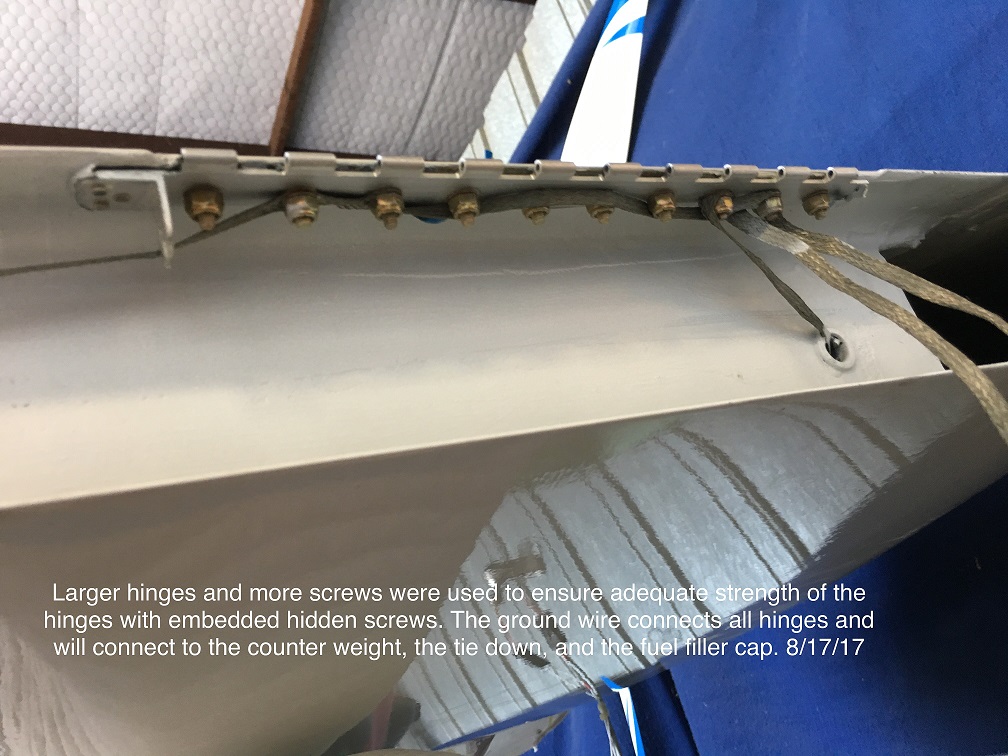
is a view of one of the aileron hinges. I used larger hinges
width wise than were called for by the plans. I also used more
screws and a thicker fiberglass pad to compensate for the deeper
recessed screw heads. The ground wire connects all of the hinges,
counterweight, and control arms with a connection to the fuel filler
surround. The tab extending down on the left side provides a tie
wire tab for locking the hinge pin in place. |
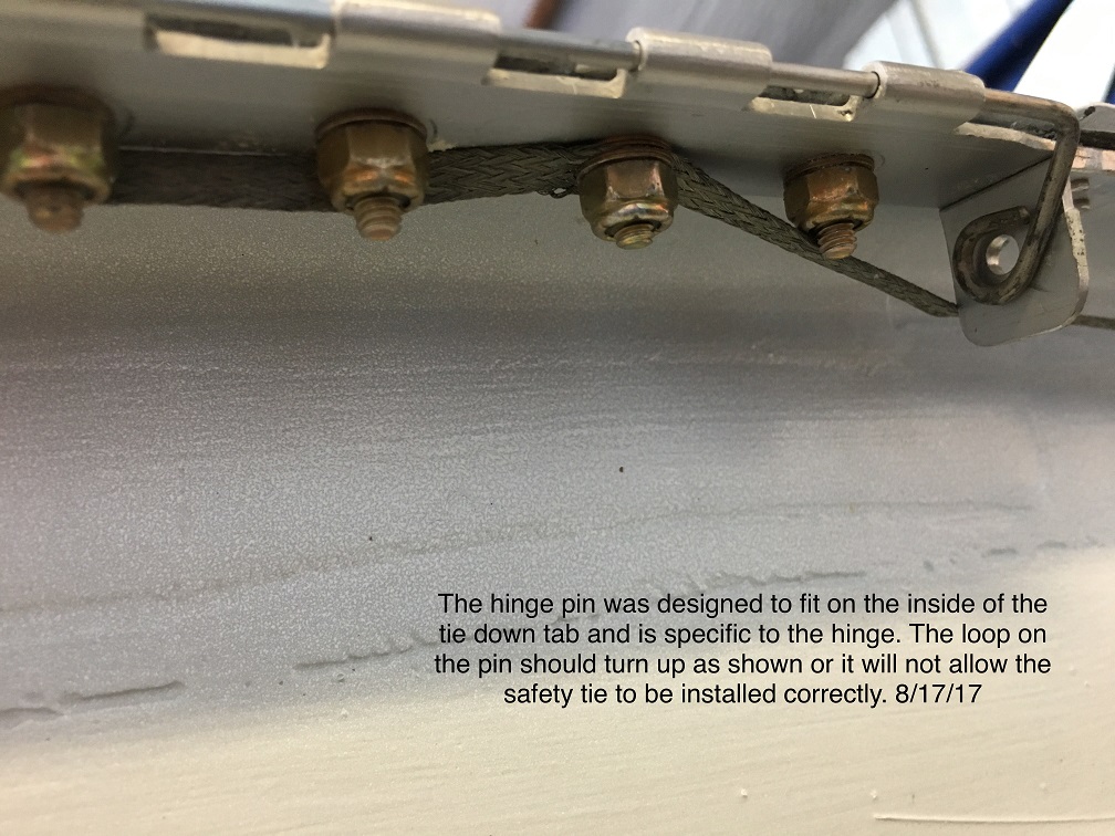 |
The
hinge pin was ground to a tapered point on one end and bent with a loop
on the other end. The loop was intended to twist into place on
the inside of the retaining tab with the loop turned up as shown.
It will not work if installed with the loop going down. This same
design was utilized on all the hinge pins. |
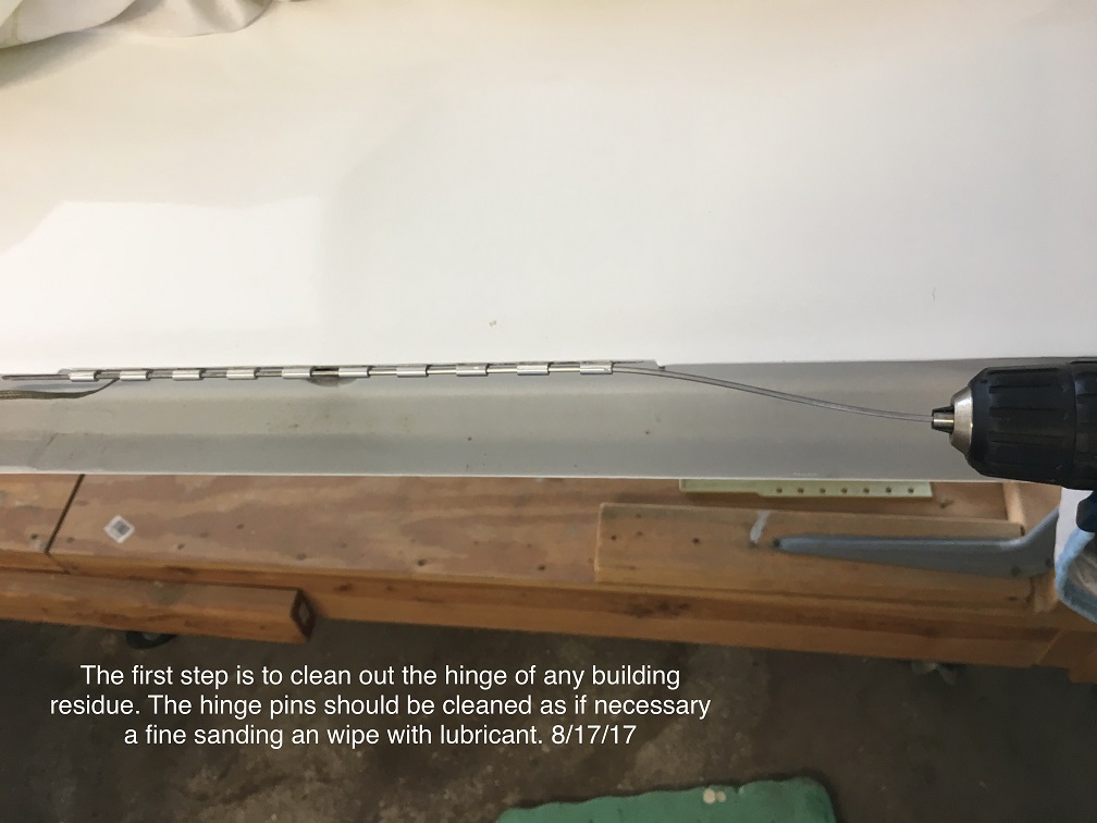 |
Both
the painting process and time resulted in some residue in the hinges
and they needed a good cleaning in order to insert the removable
pins. Cleaning and lubricating the holes is an absolute necessity
because it is anything but easy to slide the pins into place in such
confined spaces. |
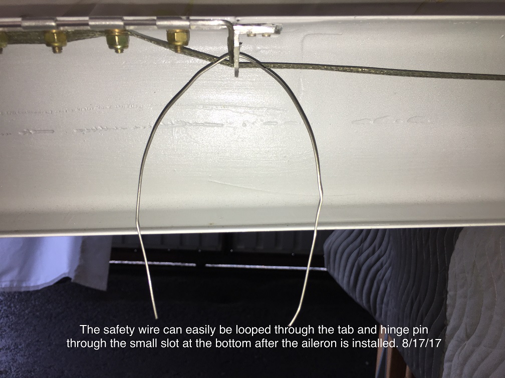 |
The
following set of photos were taken for the purpose of these
instructions and are not the actual installation photos. Once the
installation is actually underway, there is no way to get good photos. This photo shows the process of installation of the safety wire AFTER the hinge pin is finally pushed into place and the locking loop moved into place. Cut a short length of safety wire and loop through the tab and the hinge pin loop. |
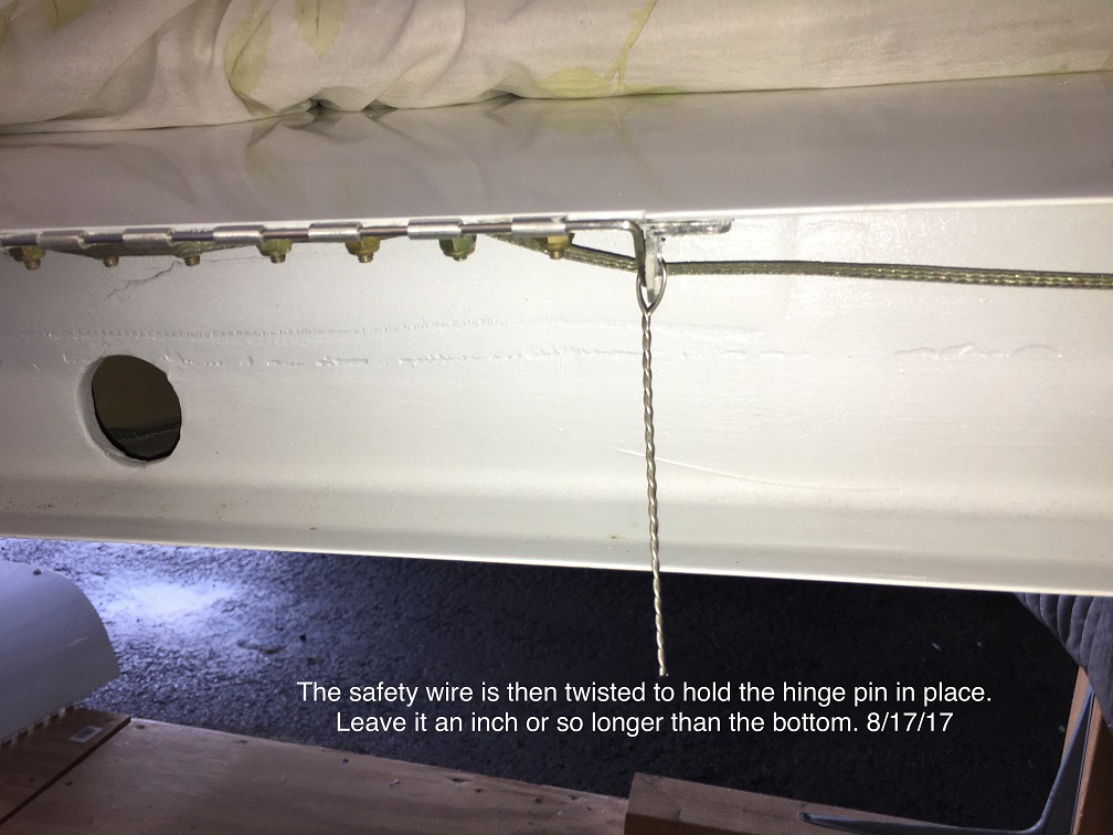 |
Pull
the ends of the safety wire together and twist as shown. Cut the
length to about 1/2 inch below the installed aileron. Don't over
twist or it will weaken the tie. |
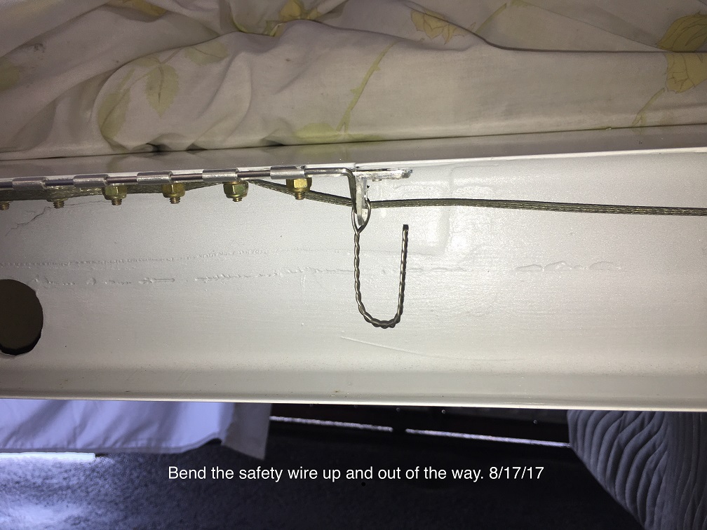 |
After
twisting use a pair of needle nose pliars to bend the end up inside the
aileron opening out of the way. Make sure it is above the line of
the lower aileron lip and won't interfere with the movement. These steps must be completed for each of the hinge pin installations for all control surfaces. |
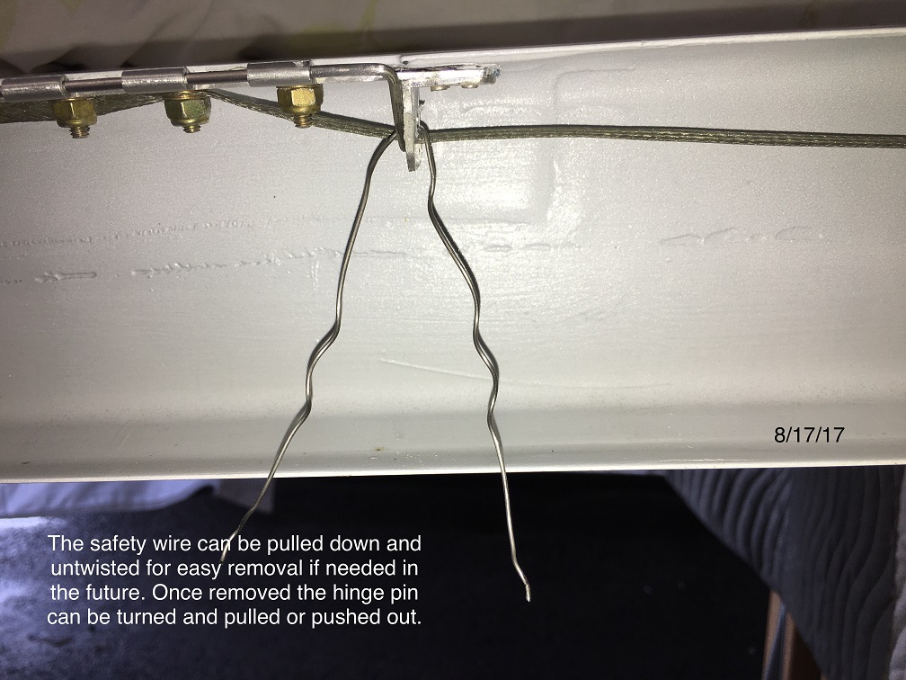 |
Removing
the control surfaces is simply a reversal of the process, pull the bent
safety wire down and untwist to open. Pull out with pliars, pull
the hinge pin loop down to clear the tab and remove with a pair of long
needle nose pliars. |
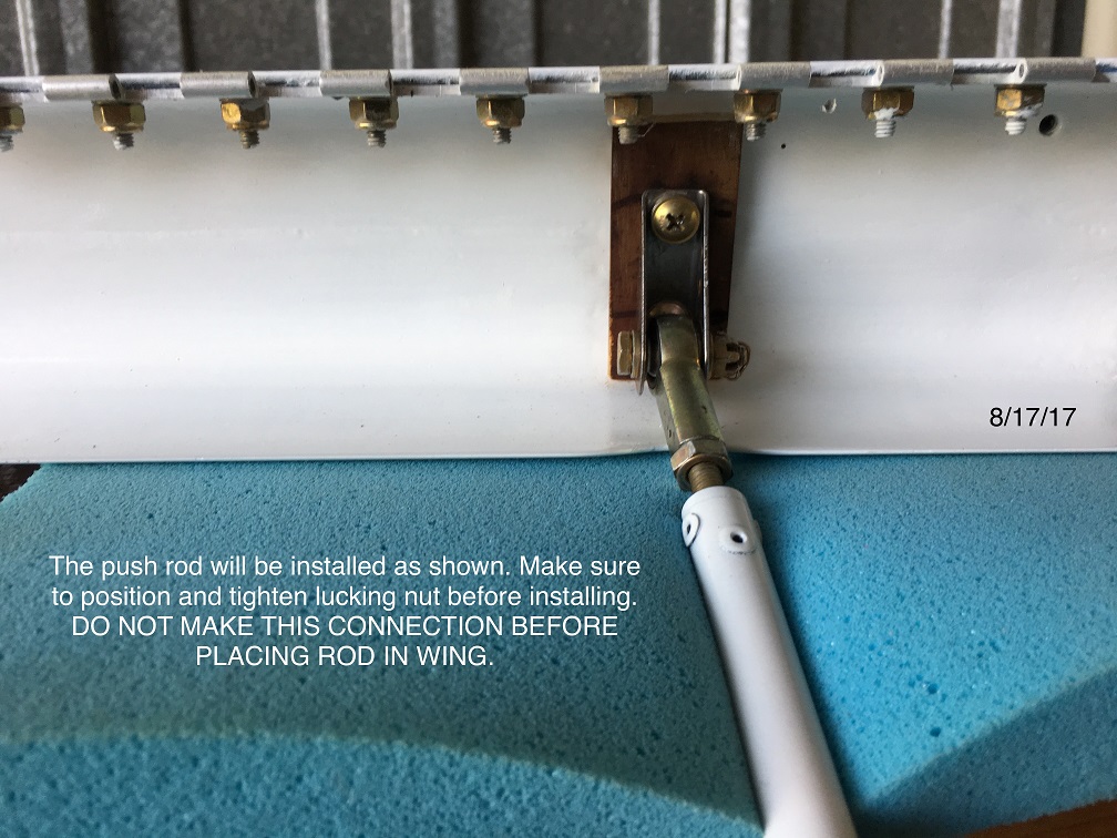 |
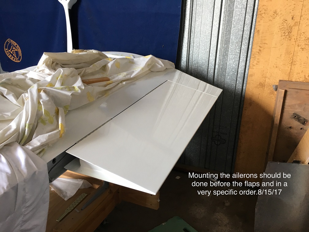
The first step in mounting each
of the
ailerons starts with installation of the mounting bracket and the
control arm. The control arm must be installed and all lock nuts
installed before proceeding. |
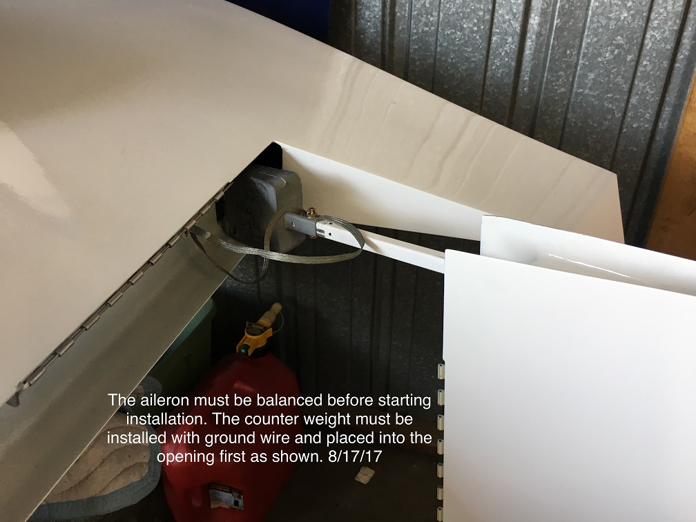 |
The Aileron MUST be balanced on
a
workbench before starting the installation on the aircraft. The
ground wires should be connected to the counterweight before proceeding
to place the counterweight into the wing opening. Make sure that
the ground wire does not interfere with movement of the counterweight
arm. Installing the counterweight through the opening requires
turning the aileron at a right angle to the wing, slipping the the
weight through opening then turning the aileron up level. This process can be done by one person but would probably be much easier with some help. |
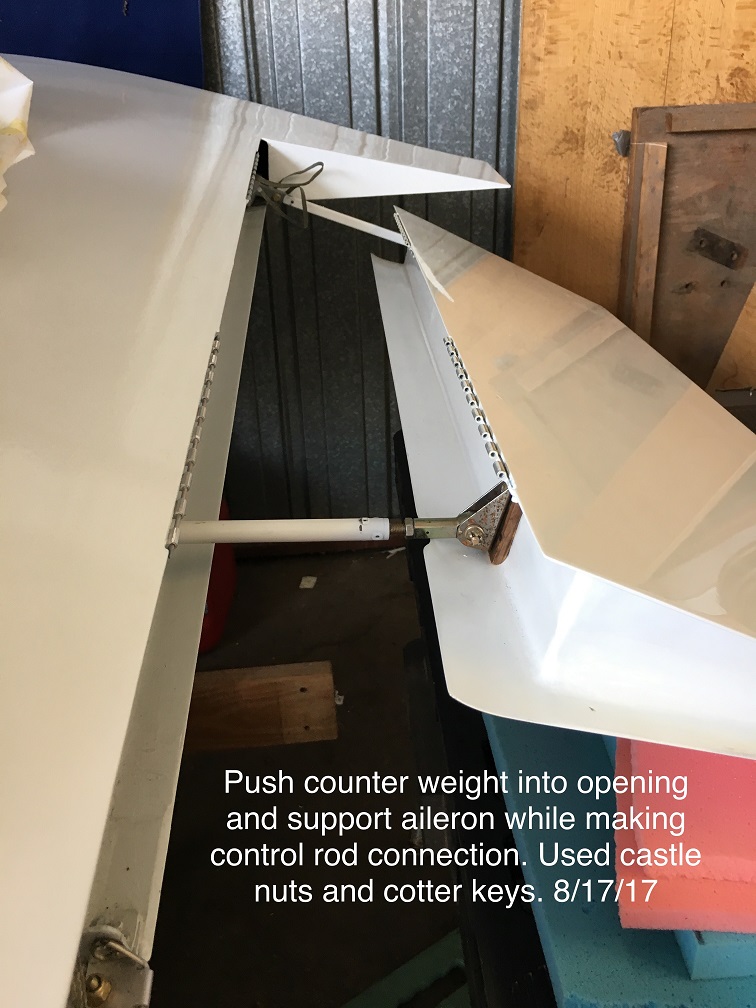 |
This is the point where a second
person would really come in handy. The aileron control rod must
be inserted into the opening before the aileron can be moved into
place. Placing the rod through the opening will require some
persistance since there two openings that must be positioned and it
took me several attempts before I was able to keep the rod in place as
I positioned the aileron into place. Trying to hold everything in
place and install the hinge pins required the use of some short
temporary hinge pins. |
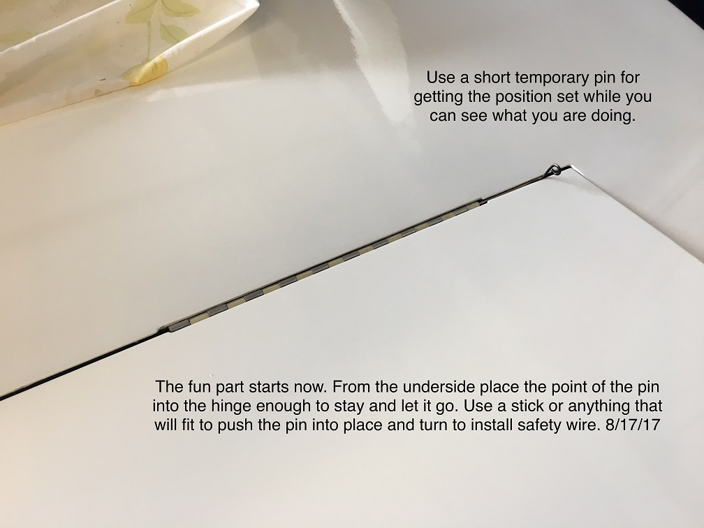 |
I made a couple of short hinge
pins
especially for the temporary installation process. They could be
slipped into place from above and would easily be removed after the
actual hinge pin is started and pushed through. Installing the
actual pin has to be inserted from below and then pushed into place
with either needle nosed pliars or a stick placed against the looped
end of the pin. The hinge pin but be started from the hinge tab
side. Once the hinge pins have been moved into place with the tab on the outside of the hinge pin loop, install the safety wire as shown in the prior photos. |
 |
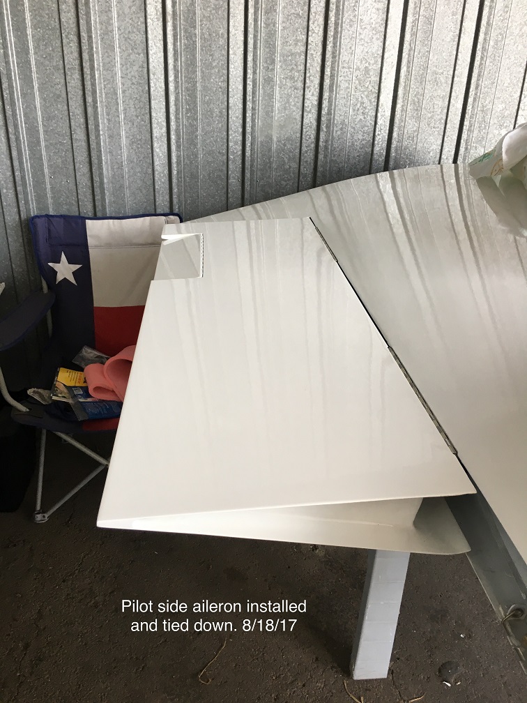
Right side aileron is
installed. It is a lot easier to install the ailerons before the
flabs since the inside hinge is easier to access with the hinge pin
since the tab is on the inside of the hinge. |
 |
The left wing aileron requires a
bit more work to install the aileron trim connections before
installation of the hinge pins. Mounting the flaps is a bit easier than the ailerons since the opening for the flaps is wider because the flaps have substantiall more travel. They are a bit tricky because of their added length and needing to install three hinges. |