
N247BR
Wing Flaps - Flap Control
| Construction Part 1 | Construction Part 2 | Construction Part 3 | Flap Controls |
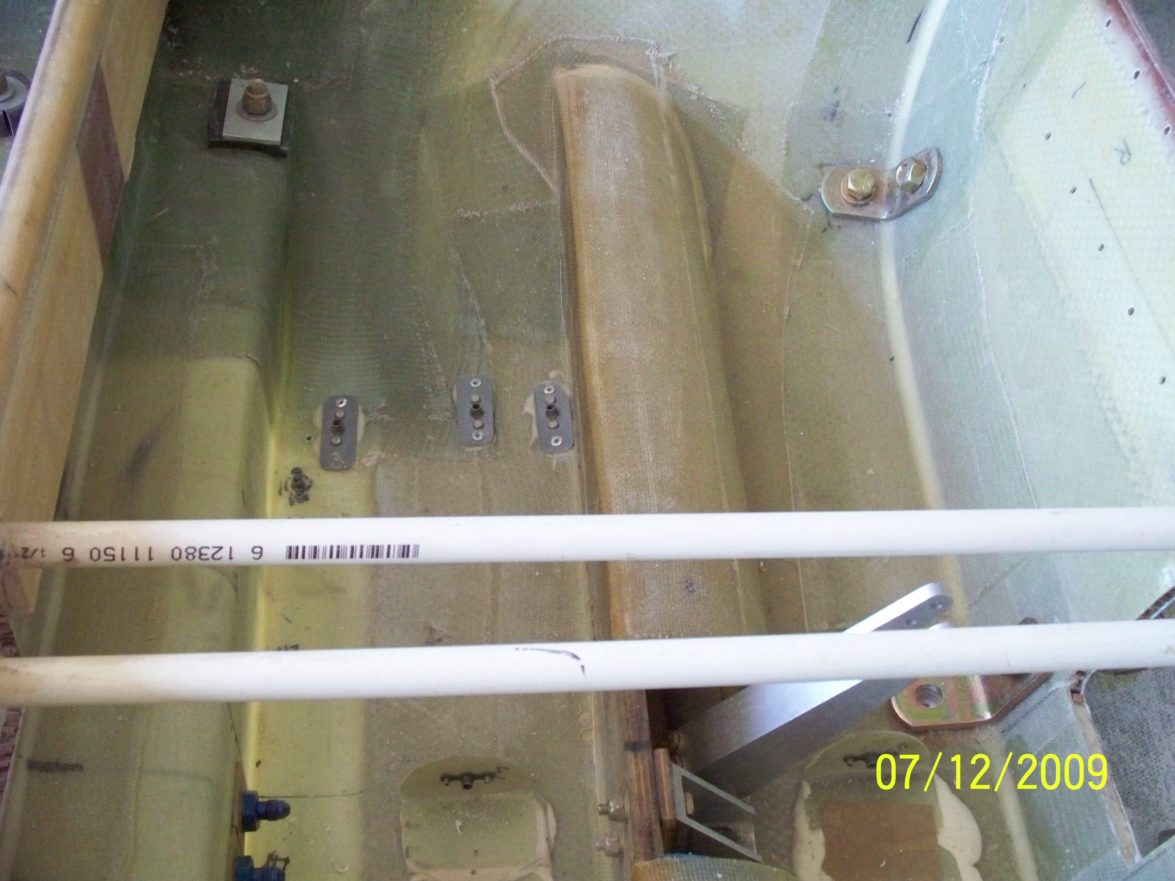 |
The
area under the the back seat between the seats is used for a pass
through of all wiring, controls, and the attachment of the linear
actuator flap control. The opening the the back seat bulkhead is
very tight for all the stuff that eventually passes through the opening. |
 |
Directly
behind the back seat I put in the mounting pints for the strobe
controller and the flap motor. The photo show the idler arm for
the elevator control. This will all be covered with a tunnel
cover. |
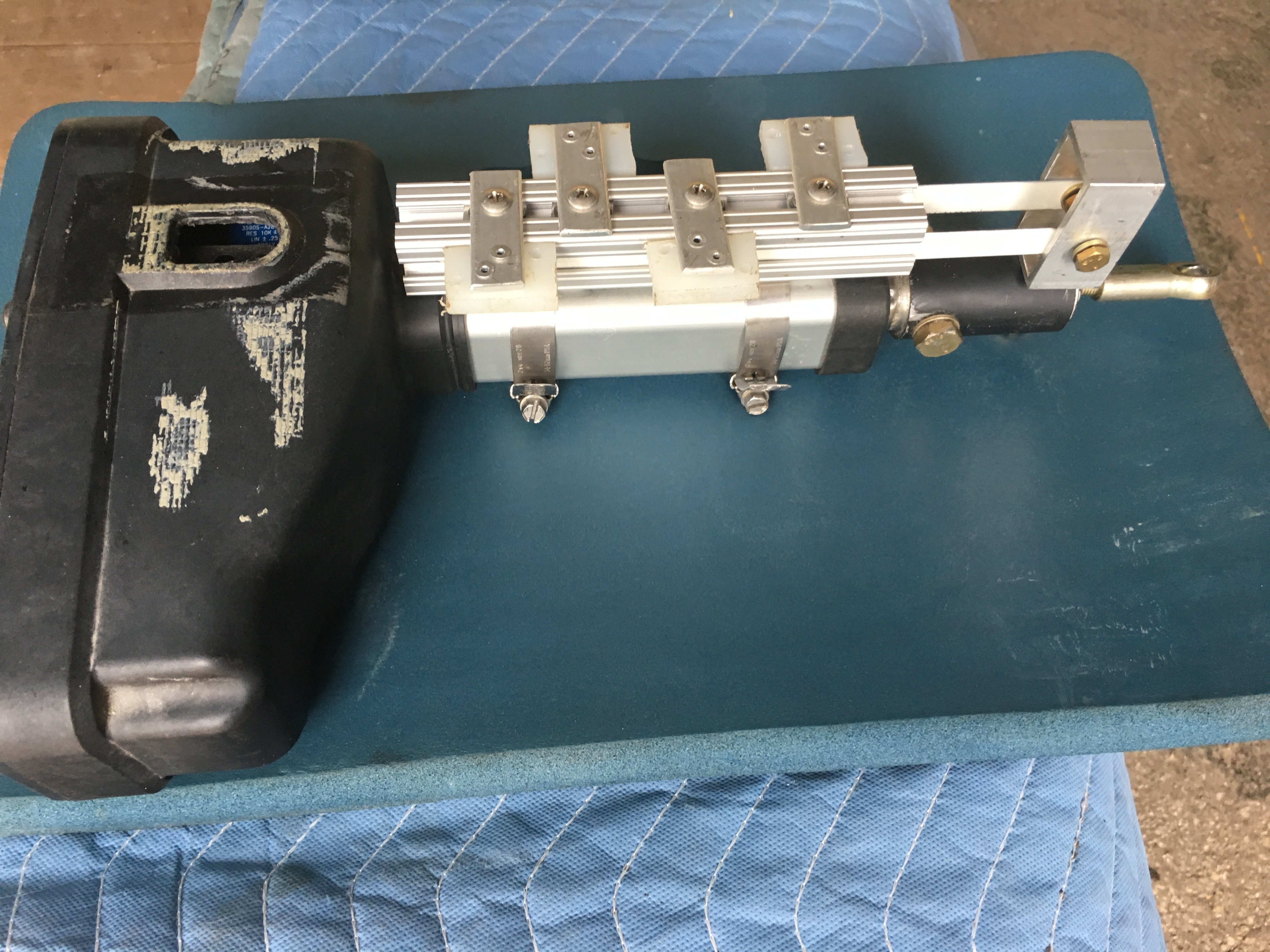 |
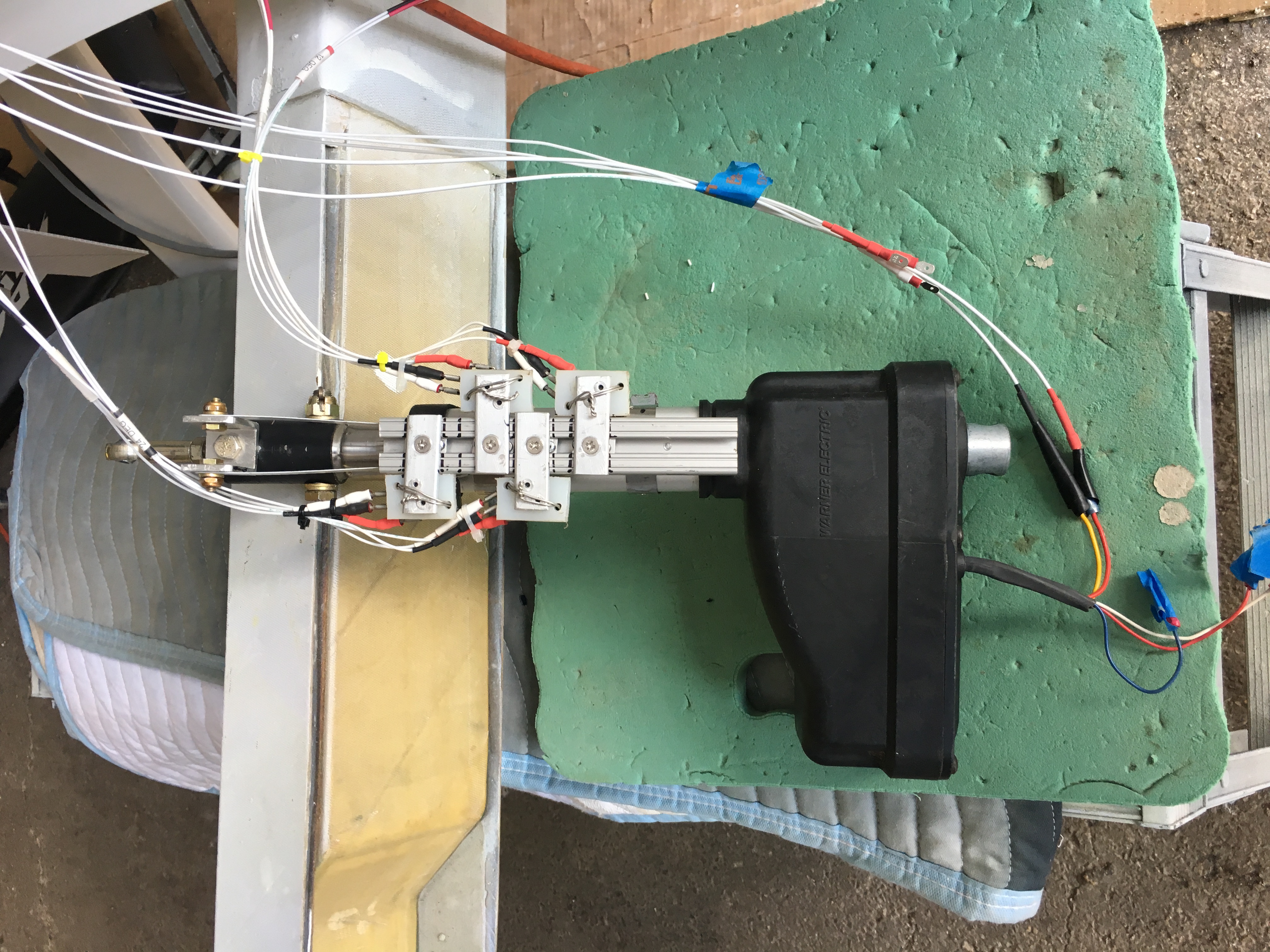
I
used a linear actuator from Warner Electric that was supposed to
contain internal limit switches. When I eventuall got around to
the installation process I discovered there were no internal limit
switches but have a build in position sensor. Not usable in the
long run. I decided to use limit switches installed into a channel connected to the actuator and tripped by a pair of hack saw blades (Saw part removed). The limit switches were rather large and resulted in the requirement for them to be alternated on either side of the channel. |
 |
Each of the switches required three wires and the actuator contained another five wires. A lot of wiring. |
 |
The
completed setup looks rather complicated but isn't as bad as it looks.
The issue was that once I installed the flap actuator the portion of
the actuator that stuck thru the rear seat bulkhead put the switches in
the opening thru the bulkhead. It just wouldn't work with the
needed movement during extending and retracting the actuator.
Time to go back to the drawing board. |
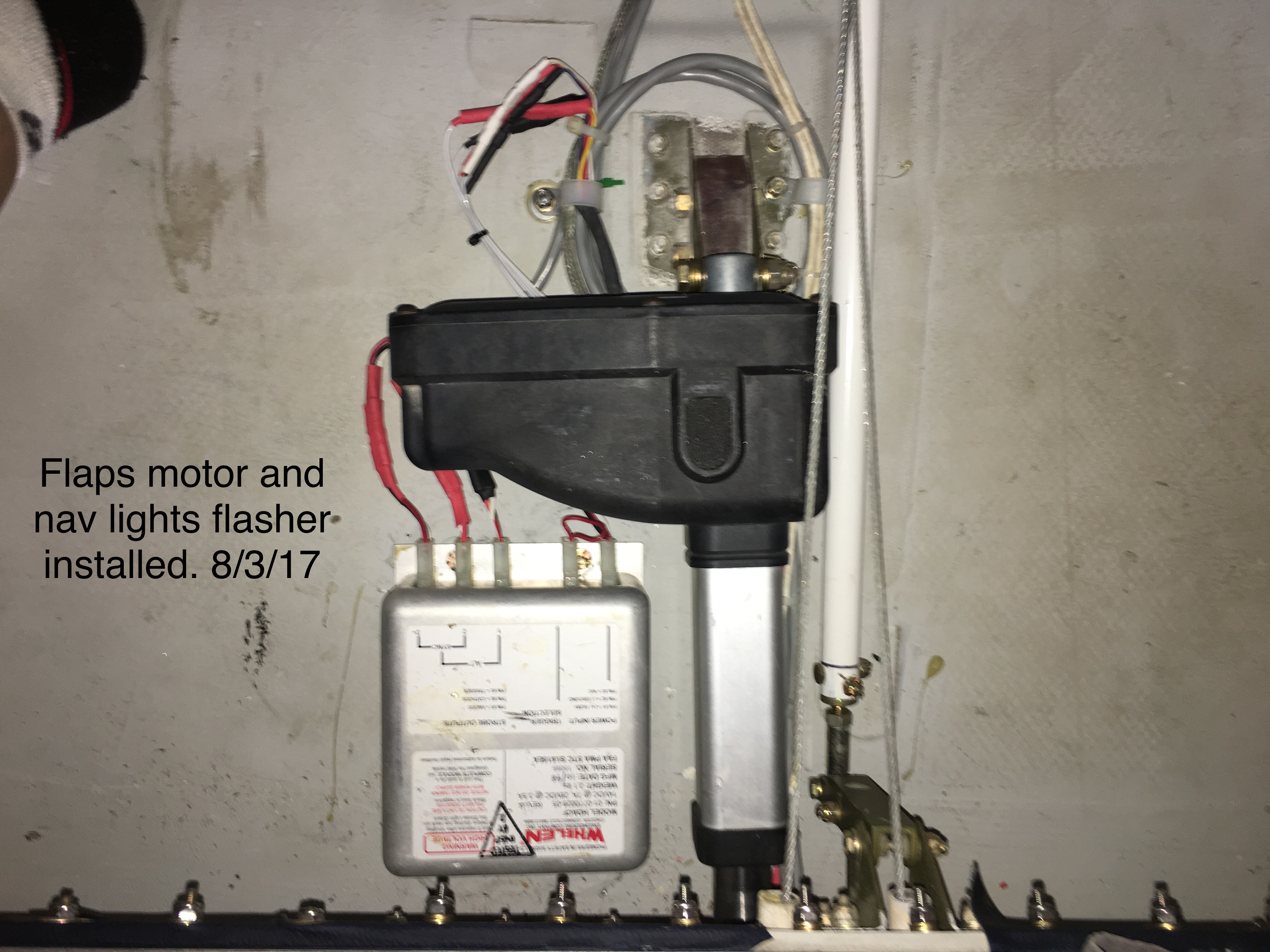 |
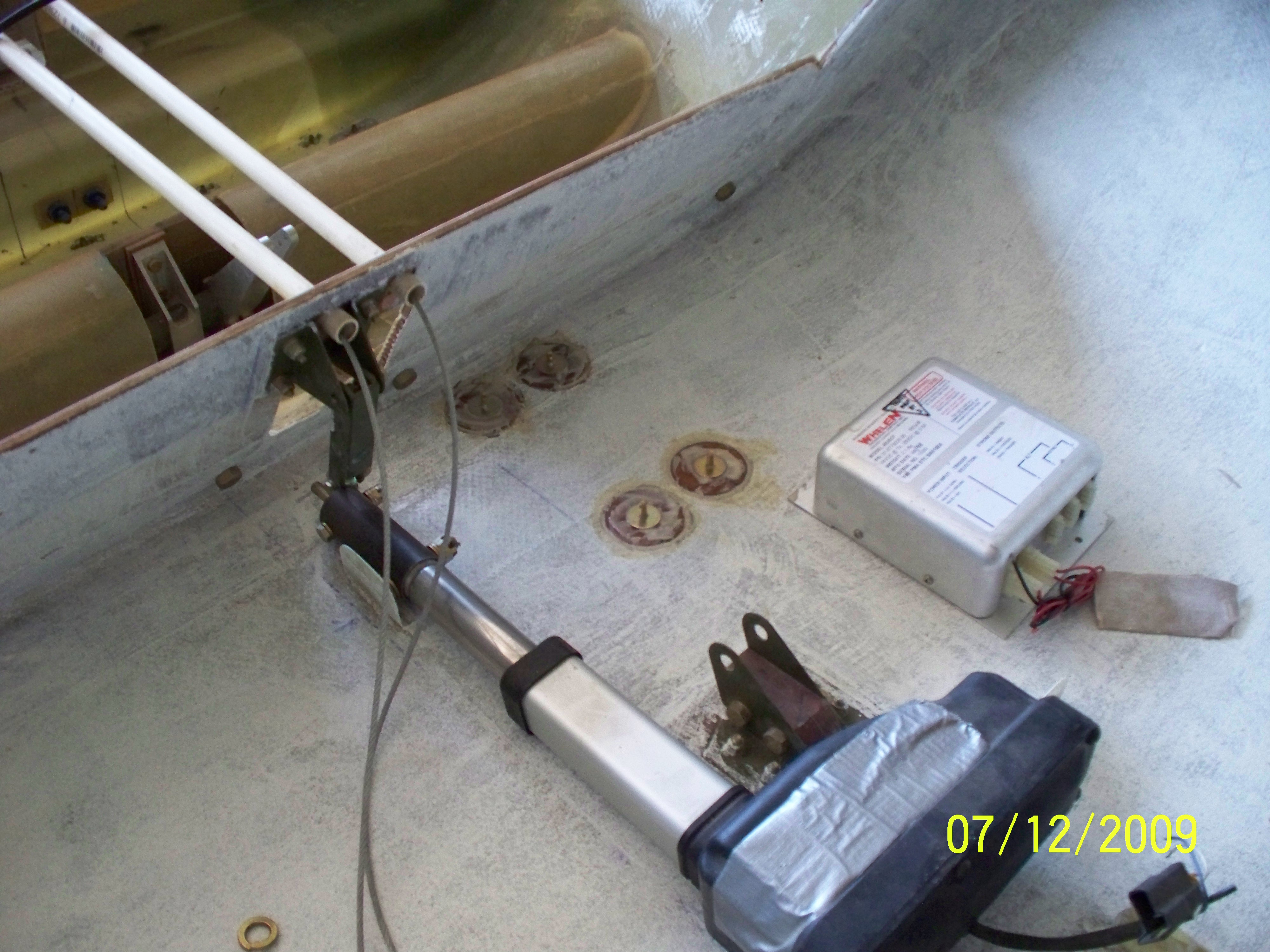
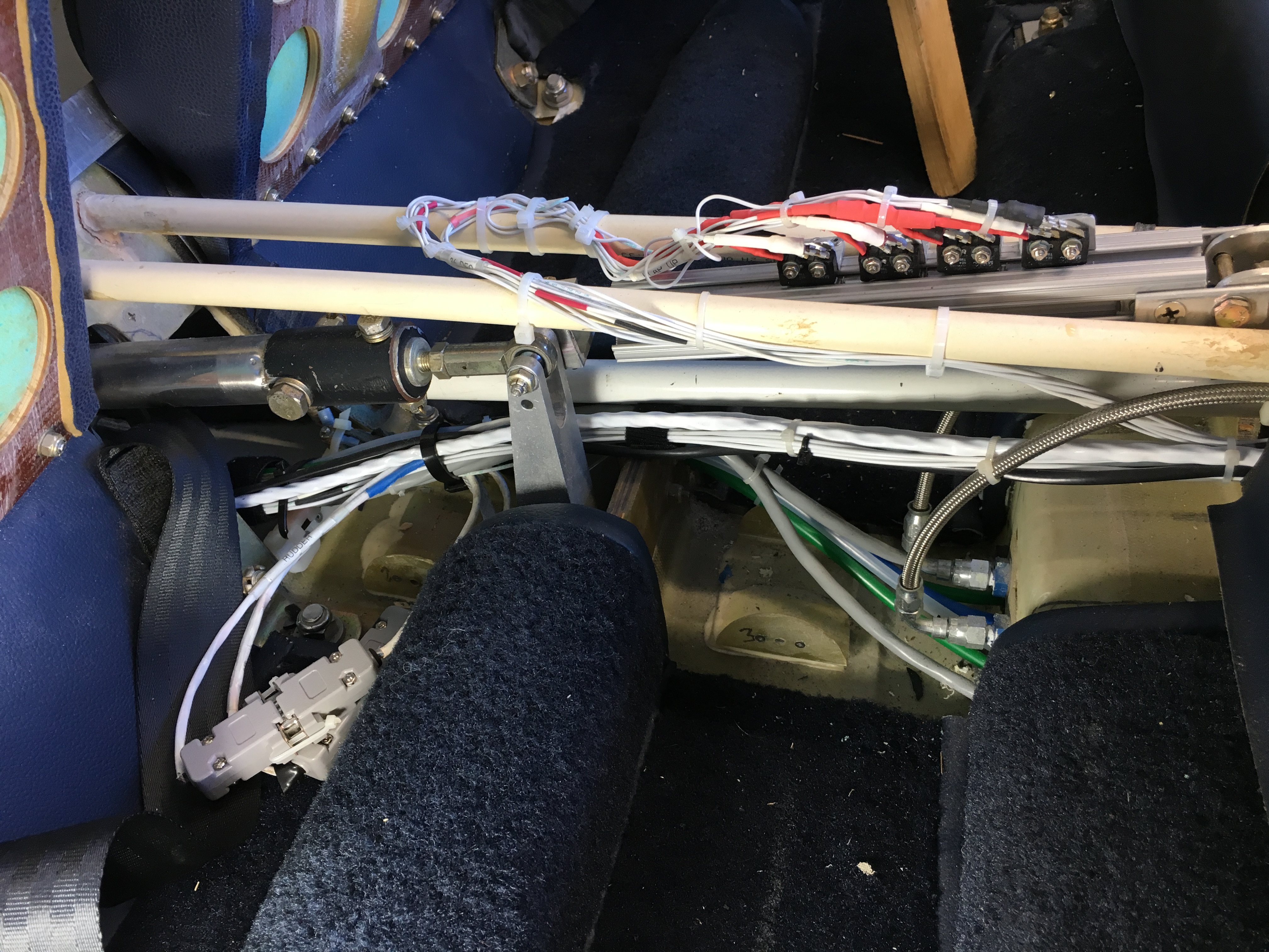
The
tight quarters for installation of the flap motor, the elevator push
rods, and the strobe lights controler can be seen but it got worse when
all of the additional wiring, pitot, static, and other lines were run
through the same space. |
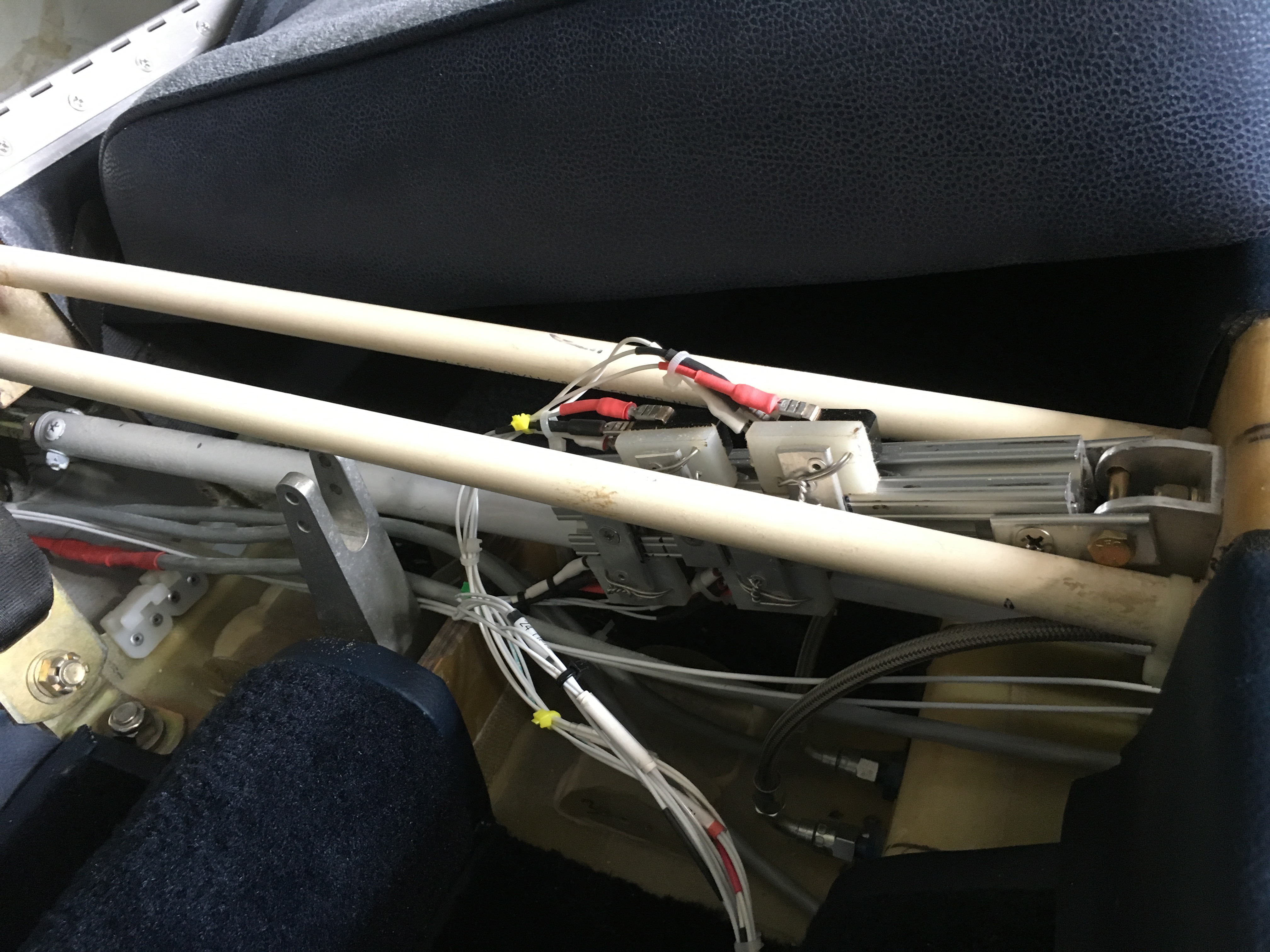 |
I
move the flap control switches to the area between the seats and turned
it sideways. This was very tight with the switches being on the
top and the bottom. Worked but the wiring was a nightmare even
though it did reduce the number of wires that had to pass through the
bulkhead opening. |
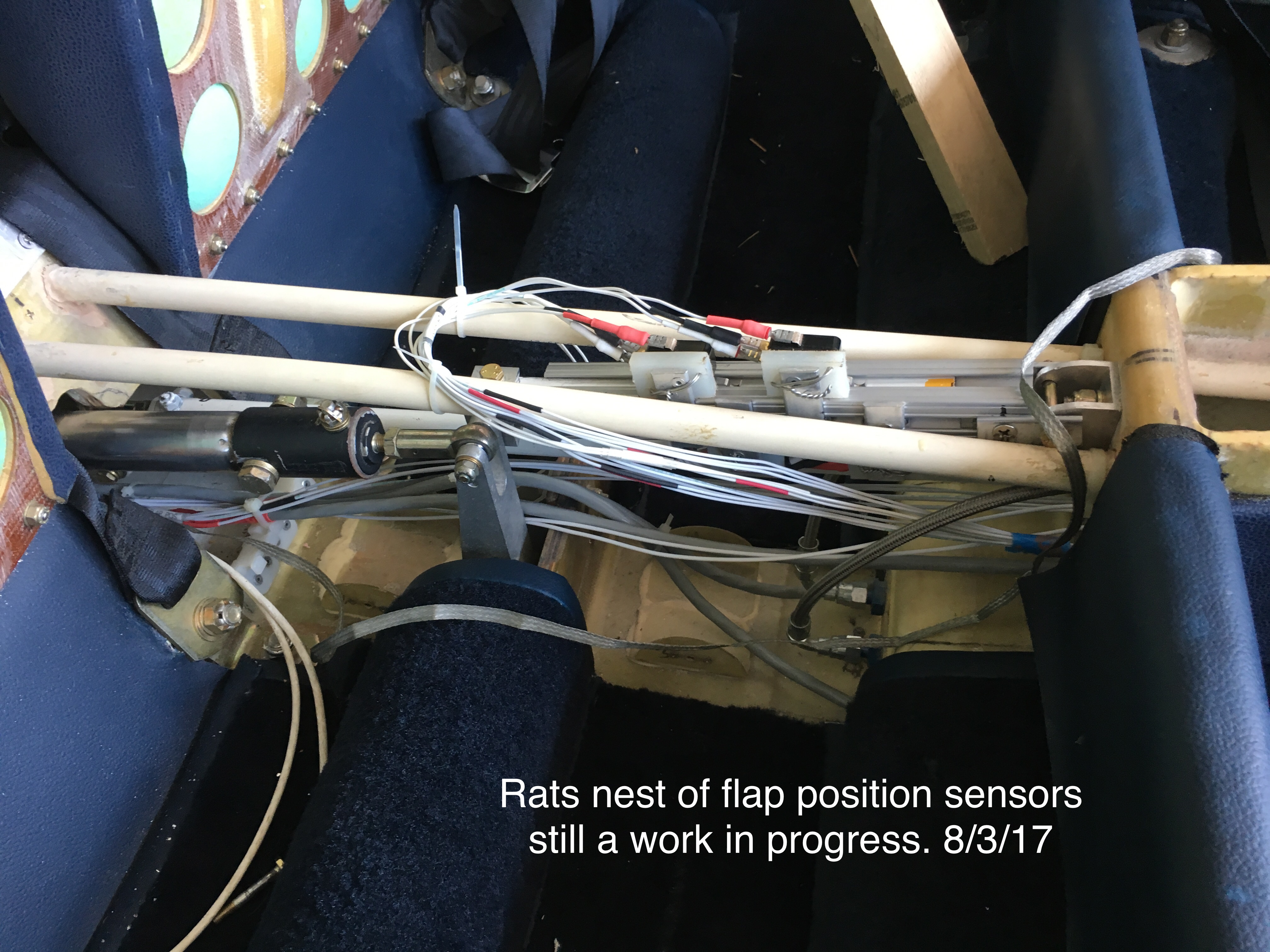 |
Well,
everything is connected and the wiring in place. With enough wire
ties and adjustment I was finally able to get everything tied down and
the switched adjusted to position the flaps. OR SO I THOUGHT!!! After hours and hours of work to get everything positioned and the wiring done I was able to accurately position the flaps at the full retracted, 12, 24, and 36 degrees. I started testing and testing but something wasn't right. The positioning down was working perfectly but about half the time, the flaps would not return to the up position. That's when I realized that the front lower switch had cracked and broken. I just wasn't happey with the whole thing and ripped it out and started over. |
| More to Come...it does get better. |
The concept was good but the Execution Stinks. |
 |
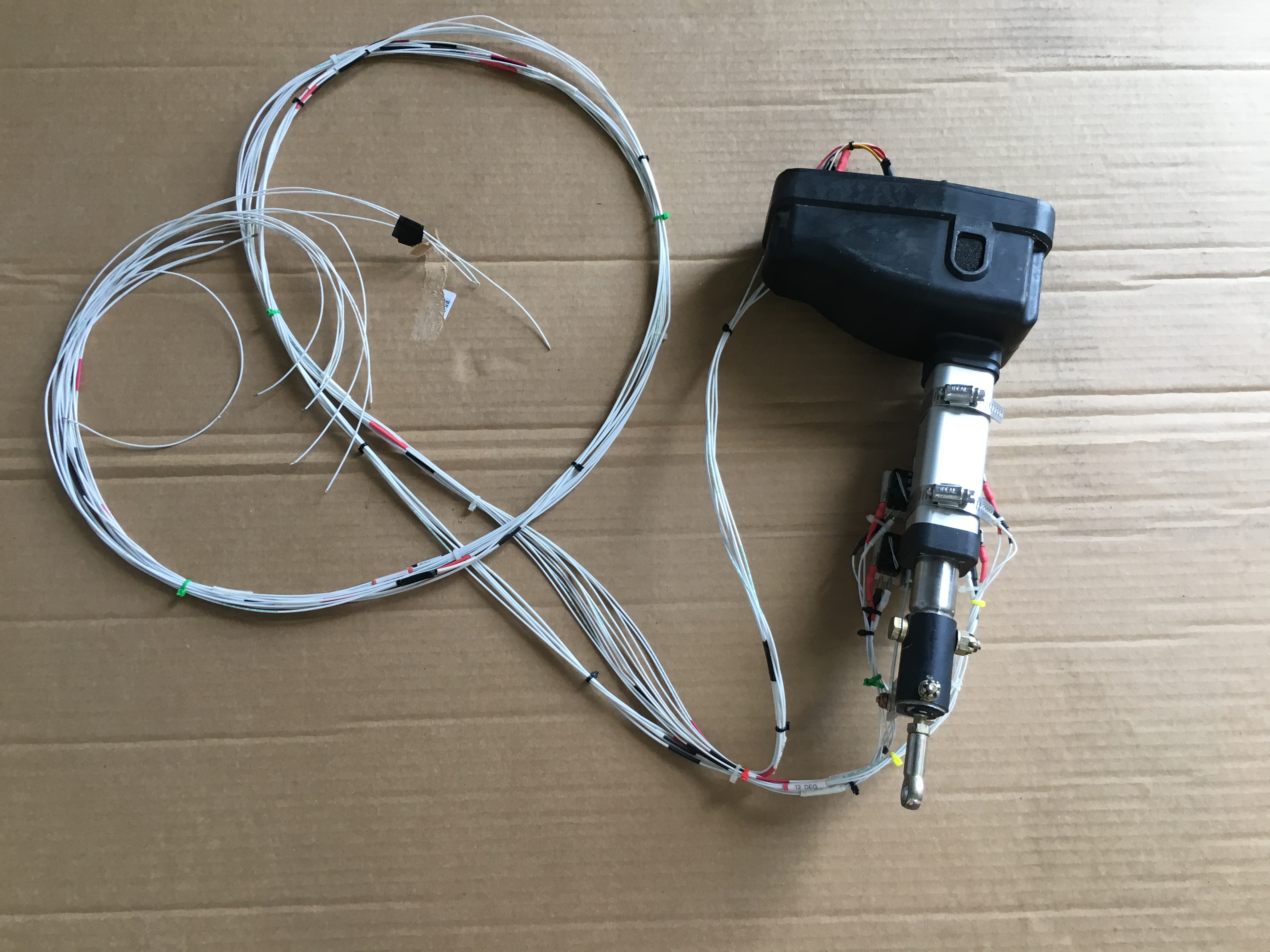
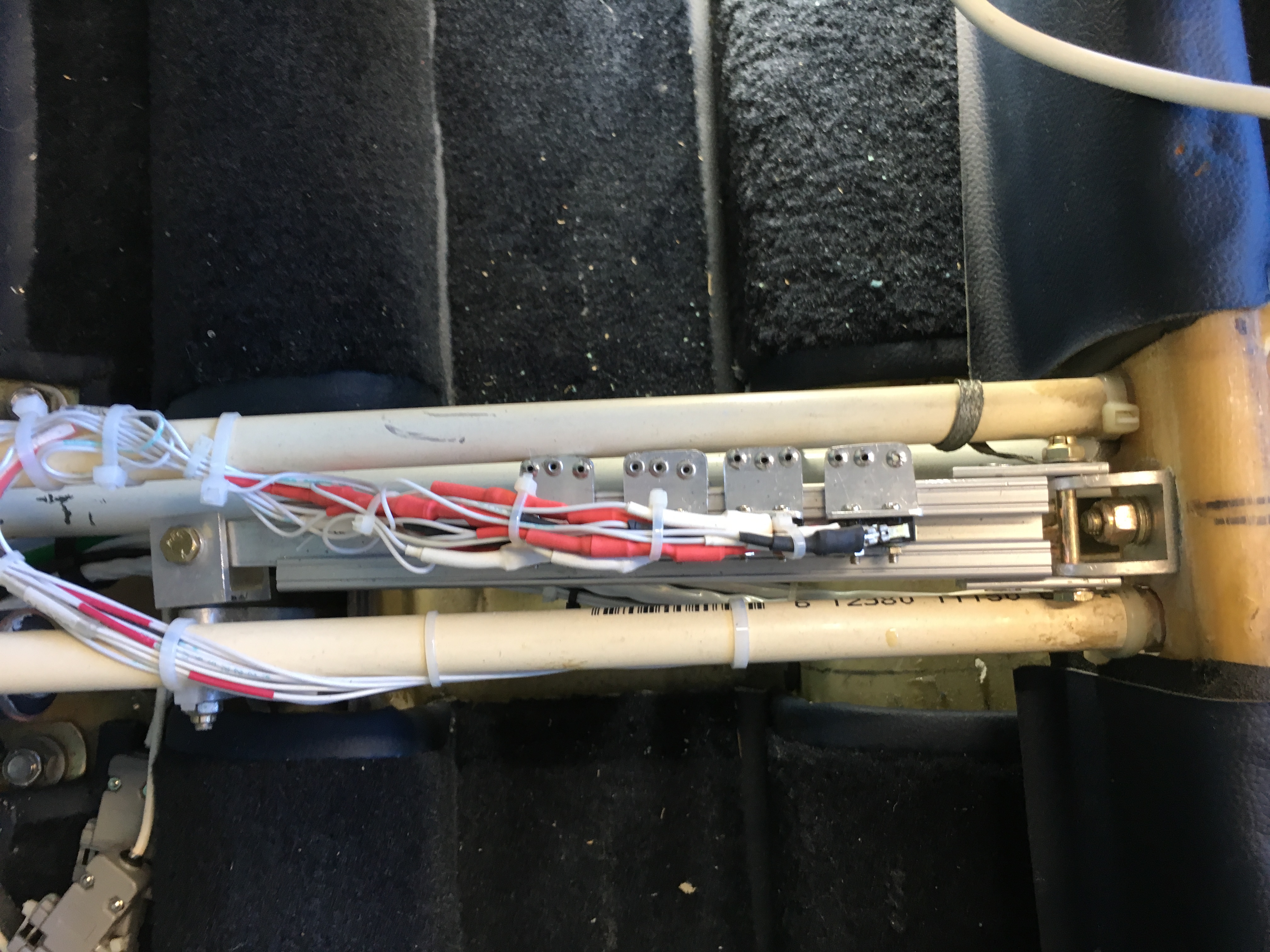
The
rebuild flap control unit can be seen installed using the much smaller
micro switches. I had to redo all of the connectors to the
switches since the original switched used the .25 inch push tabs while
the new switched use the .187 tabs. They are much smaller and allowed
all of the switched to be installed on one side. |
 |
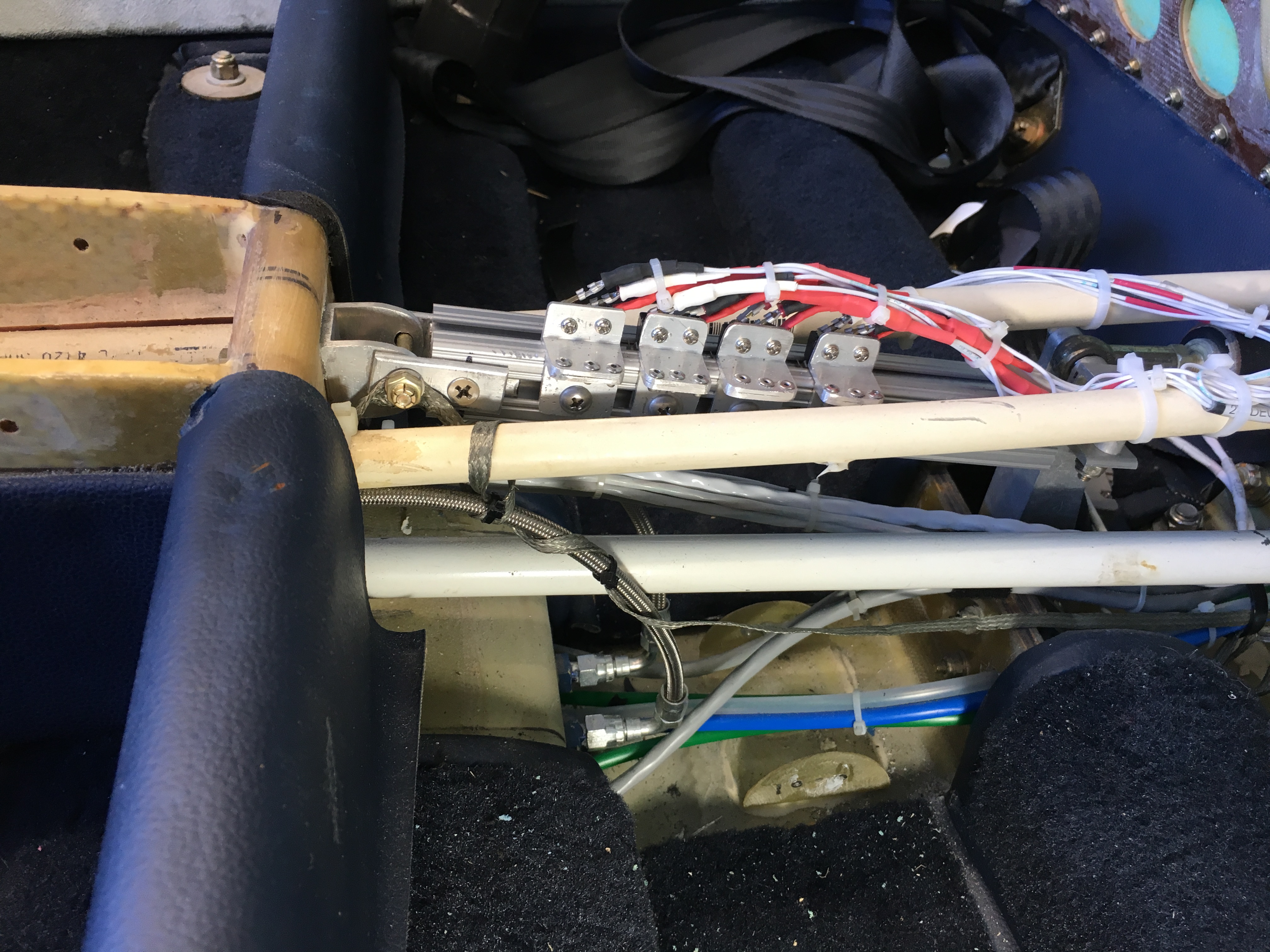
A
top view shows the tight formation and how the switches sit directly
over the open channel. The switches are triggered as a thin
aluminum blade slides up the center channel. |
 |
This
view shows the switch mounting tabs and their connection to the side of
the channel. The tabs are held in place with a screw that
connects to a tab inside the channel. This system works exactly as I had wanted it to and allows for easy adjustment of the flap position. |