Tri-R Technologies TR-4
BUILDER'S MANUAL
This Builder's Manual is NOT the official manual as published by TRI-R Technologies.
WING ASSEMBLY
Quick Links to Wing Assembly Sub-Sections:
SPAR
INSPECTION
MAIN SPAR AND OUTBOARD SPAR PRE ASSEMBLY
WING
ASSEMBLY JIG
UPPER
WING SKIN PREPARATION
REAR
SPAR PREPARATION
AFT
RIB INSTALLATION
MAIN
SPAR
SPAR
FILLER BLOCKS
TRIAL FIT
UP
FUEL
OUTLET
FUEL
MEASURING PROVISION
ANTI-SLOSH
VALVE
FUEL
VENT LINES.
HARD
POINT FOR THE AILERON BELL CRANK
BONDING
UPPER SKIN ASSEMBLY
PITOT
STATIC LINES - LEFT WING
SPAR
POCKET CLOSE-OUT
GAS
CAP
FUEL
PROOFING
AILERON
HOLE IN REAR SPAR
AILERON
HOLE IN MAIN SPAR
WIRING
CONDUIT
AILERON
BELL CRANK
PREPARATION
OF LOWER WING SKIN
FUEL DRAIN
COCK
INSPECTION
PANELS AND ACCESS COVERS.
AILERON
BELL CRANK INSPECTION PANEL
SUGGESTED
PITOT TUBE FABRICATION
OTHER
ACCESS COVERS
INSTALLATION
OF LOWER SKIN
STIFFEN
TRAILING EDGE
INSTALL
HINGES
INSTALLATION
OF WING TIPS
ACCESS
PANEL CONSTRUCTION
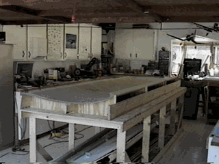
The first step for the wing assembly is to fabricate an assembly jig similar to the sketch shown. The upper contour of the airfoil should be traced from the full size wing jig pattern provided and carefully cut from 1/2 (or thicker) plywood or particle board. Cut at least four cradles. Cut far enough around the nose radius contour (as shown on the pattern), to provide a positive reference for positioning the nose of the upper skin (the wing is built upside down in the jig). Some of the materials may be salvaged from the shipping crate, but most will have to be procured locally. Be sure the stringers are straight and not warped (reinforcing the stringers with straight strips of plywood, or ripping them from 3/4 ply may help ensure that they stay straight). The stringers should be located such that the center stringer is in line with the main spar, and the rear stringer centered beneath the rear spar (the pattern shows the location of the center stringer and the aft stringer). It is recommended that the stringers be 12 feet long, and the outer cradles, outside edges be 130 inches apart (about 2 inches shorter than the wing skins). The assembly fixture should be securely attached to a table or saw horses at a convenient height for working on. Leveling is the accepted way of setting up such a jig, but straightness, and lack of twist are the really important parameters. When positioned, secure in place (to the floor) so the jig will not move around and twist during fabrication (using bondo to glue the supports to the floor is recommended if practical). This same set up is used for both wing halves, so it is worth taking the extra time to feel confident with your set up. See figure XX that shows the top wing skin mounted into the wing jig. This 4 ft. by 12 ft. table was constructed to build the wings and can be used for many other assembly operations.

Figure -7, Right wing skin mounted in jig.
Factory Update!
FOUR PLACE WING CONSTRUCTION TIPS
With the introduction of the four place quick build wing option, we are deriving more experience in dealing with the wing assembly issues. The most significant item is that the wing skins with the 3/8ths thick foam core, are extremely stiff. This coupled with the tendency of the tooling and finished parts to overcurl, requires some cautions in constructing the wing jigs, and securing the wing skin in the proper contour in the jig. Firstly, the jig should be made with considerable structural stiffness, and be anchored to a rigid table or surface. Bondo, and or screws with shims are suggested to anchor the jig and surface together. Staightness and lack of twist are the most important parameters to observe at this point. Those two factors are more important than being level, although making the system level helps in obtaining the straightness and lack of twist..