The following photographs give the sequence of steps to produce a flush fitting,
round cornered, easily removable access panel. Construction procedures follow
each photo.
| 4 Tinnerman washers 100 Deg. counter sunk |
| 4 AN507-832R10 (832 5/8 in.) flat head screw for temporary hold down. |
| 4 AN507-832R12 (832 5/8 in.) flat head screw for hatch cover. |
| 8 AN426AD-3-4 flat head rivets |
| 4 MS21047-8 nut plate (K1000 series) |
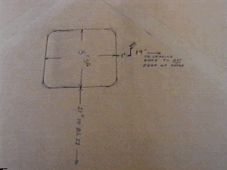
Lay out the access cover location by obtaining two reference edges, either
the trailing edge or the leading edge and the inboard wing edge (BL-22).
From these starting points, locate two corners of the opening on one edge,
such as, closest to the main spar. ( the spar hatch in fig. 6-35 starts one
inch aft of the main spar )
Obtain the center line of the hatch 90 deg. from the first line. In fig.
6-35 the center line is one inch inboard of the center line of the wing bolt
bushing. This is to allow ample clearance from the rib.
Now measure 2.5 inches each side of the center line to get the width of the
opening. ( in this case 5 in.’s)
Draw the outline.
Radius the corners a minimum of ¼ inch.
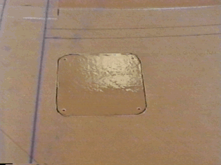
Using a thin blade hobby saw (.015 in. blade thickness), use the tip to start your cut, progressing through both layers of glass, cutting the straight edges only. A Dremel tool and a small cutter were used to cut the radii on this hatch. A wire saw may also be used.

Figure -43: Hatch layout.
After the hatch has been cut from the skin, remove about 1/8 in. of foam
from around the edge.
Fill this recessed edge using a dry micro mix.
After curing, smooth the edges and sand to a slight chamfer to allow for
easy insertion and removal.
Using Tinnerman washers, mark and drill the four mounting holes. Drill for
8-32 machine screws.
Counter sink the holes using a 100 Deg. countersink. Sink the holes deep
enough so that the back side of the washers will sit flush with the skin.
Using 3m 77 spray adhesive, LIGHTLY coat the back of the hatch.
Cut a piece of acetate or plastic 1/8 in. larger than the cutout in the skin,
so that the gap between the hatch and the cut edge is covered. Apply the
acetate to the hatch cover.
Move the wing skin into a position so that access to both sides is possible.
Place the access cover carefully into the opening. Insure that it is in the
same way it was cut out.

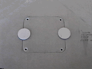
Figure -44: Acetate glued to back of cover. Holes drilled in cover.
Obtain two small pieces of scrap wood.
While the cover is inserted in its cutout, carefully glue the pieces of wood
to the face of the hatch making sure that the hatch is flush with the surface
of the wing. If necessary use four pieces of wood to obtain a flush fit along
all edges. Note the countersunk mounting holes.
Make sure you clean the area to remove all the wax parting agent on the skin.
Do not use to much glue, you need to get it off again without damaging the
skin.
After tack gluing, turn the skin over. Make sure that the acetate has not
shifted. Make sure no grease or oils have contaminated the area.

Figure -45: Temporary mounting.
Cut two pieces of glass cloth to fit over the complete access panel and overlap
the skin by 1 in. on all sides.
Pre wet the skin area and apply the glass cloth.
On the four corners where the nut plates will be mounted, use scrap pieces
of cloth and apply three more pieces diagonally across all four corners.
Make sure that the diagonal pieces extend far enough into the cover area
to hold the nut plates.
Using acetate or plastic over the lay-up, remove all air bubbles.
When cured, remove the cover and draw align 1/8 in. in from the edge around
the inside of the access opening. This will be the cut line for the panel
rest flange.
On each corner, draw a diagonal cut line, allowing enough room to mound the
nut plate. Make sure that there is enough space to counter sink the rivets
without coming to close to the edge of the flange.
Draw a 1/8 in. radius on all corners to be cut.
Now cut along the line.

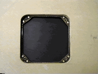
Figure -46
After cutting the center out of the access panel opening, insert the access
cover.
Using the pre drilled holes in the cover, drill through the nut plate mounting
areas.
Remove the access panel, and using screws just long enough to enter the nut
plate by about three threads, temporarily mount the nut plates in their
respective positions.
Using a #40 drill, drill the rivet holes. Counter sink for the rivet heads.
Using a rivet (hand) squeeze, install the rivets.
Done!