Installation of Lyle Hendrick’s door locks
By Bill Schertz
Locks from From Lyle Hendricks - Hendricks Mfg. Inc.
www.HendricksMfg.com
(designed by Vance Jaqua)
Installation of Lyle Hendrick’s door locks
- PART 2
Lyle’s locks arrived while I was working at fitting the doors/windows,
so I started the process of installing them.
There are several things that must be considered in installing the lock
mechanisms:
-
The locks are designed to be essentially flush with the carbon fiber outer
door skin. However, the opening in the skin can only be cut after the skin
is bonded to the door.
-
You need to have access to the assembly from the inside of the plane. This
can be accomplished with a removable arm rest. The lock assembly needs to
be securely held in position against the outer door skin, but there are no
mounting holes.
-
I feel you need to be able to assemble all components into the door from
the inside of the door after the outer skin is bonded in place. A means to
test access is required.
-
The locking mechanism is secure, but the motion of the assembly is not trivial
to deal with in making it work with drive pins.
Here is how I am mounting the locks:
-
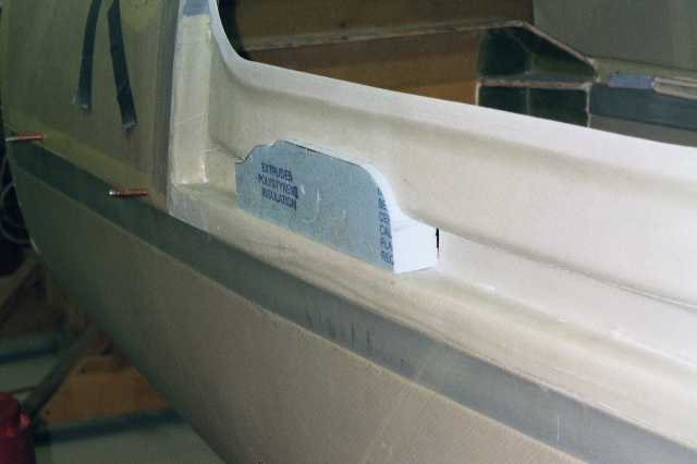
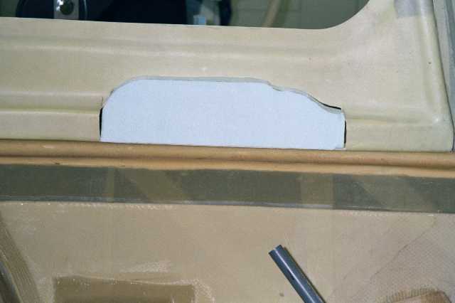
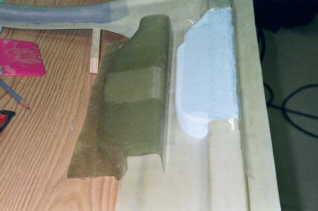
I constructed the arm rest by cutting out a section of the door channel,
shaping a piece of blue foam to the required shape, and then covering it
with tape and laying fiberglass over it like a mold. It then can be popped
off and trimmed to be attached with screws and nut plates. See photo below
-
Installation of window
-
Prior to going full tilt on the door handle, I put the windows into position,
bonding them to the inside skin. A technical counselor, noting the fact that
the window and door frame had some slight shape differences, recommended
using drilled holes and clecoes rather than the tape-it-down method mentioned
in the manual. I could not get tape to hold the window into position reliably,
and there is no margin for clecoes outside of the plexiglass area. If you
do this, be sure to get an acrylic drill bit (different shape), and after
drilling the holes, use a counter sink to relieve all the holes edges to
remove the sharp edge.
-
Master plywood template
-
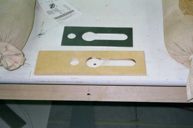
Lyle made us a template from steel. By taping it to a piece of ¼" plywood,
I could then use the router table and a pilot router bit to cut a duplicate
out of plywood. Extreme care needs to be taken, since the metal template
is so thin, it is difficult to catch the edge of the ball-bearing.
-
The plywood template then needs to have the hole for the lock opened up a
little to let the lock sit down into the template flat. I did this on a drum
sander, having marked the larger diameter needed.
-
Acrylic template to mount lock on for positioning
-
With the plywood template now done, it can be used to make an acrylic template,
using hardware store acrylic. Make the acrylic piece large enough to span
the bottom of the door to the bottom of the window. Position the lock set
into the template with carpet (double sided) tape, and you can move the lock-set
around in the opening until it is correctly positioned to be able to open
and close. I found that about 1" up from the bottom of the channel was about
right. I then cut a short piece of ¼" plywood to 1" width, and carpet
taped it to acrylic, butted against the bottom of the lock. This is now the
mechanism for positioning the template.
I then drilled two holes for clecoes through the bottom door flange, secured
it, and then drilled through one of the existing holes in the window frame,
from the inside out through the acrylic template to allow a third cleco to
hold the template and lock assemble into position. About this time, the carpet
tape holding the lock in position let go and had to be replaced.
-
Drawing of holding assembly
-
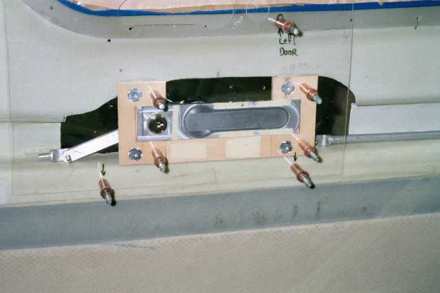
The holding assembly that I came up with is shown in one of the attached
drawings. It consists of two pieces of U-shaped plywood that will be bonded
to the inner skin with flox, these pieces have 8-32 T-nuts buried in them,
and then a ¼" thick plywood piece is screwed to them to overlap the
lock and secure it. Since the thickness of the metal is slightly less than
¼", I used some thin modeling plywood to shim it to a tight fit.
(Note: Double click on drawing for full readable
view.)
The combination of a U-shape, and the overlapping securing board makes for
a secure attachment (I think). The U-shaped pieces are held with clecoes
in the jig for fitting purposes.
-
Need for idler arm on front push rod
-
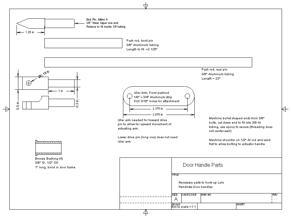
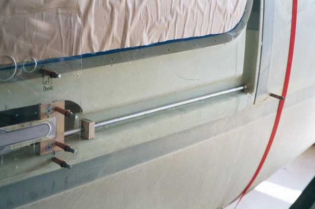
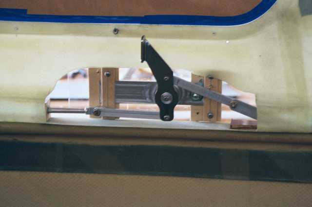
I found it necessary to build an idler arm from the front actuating rod of
Lyle’s to the front drive pin. The front rod rises significantly when
the handle is rotated, and you want a straight push-pull action from the
drive pin. You can see in the photo’s how this is done. A ¼" thick
bakelite piece acts as a surface for the idler arm to slide on, and the ½"
plywood guide blocks will be replaced by phenolic before being bonded into
place. The block for the rear pushrod, (shown below as plywood ) needs to
be removable in order to get the components in after assembly of the door
skin.
Now that all of the pieces have been fabricated, they will be removed, the
outer skin bonded into place, and then the acrylic template will be used
to locate where the cutout for the lock needs to go. The template will be
positioned by the existing holes in the door inner skin, and therefore it
should be in the right place. A pilot bit should duplicate the keyhole and
lock holes, so that the lock will fit. Then the lock-set will be positioned,
the plywood U-shaped pieces bonded to the inside of the outer skin, and the
assembly can be assembled from the inside of the door.
Lyle’s metal template may be borrowed by the next builder, with the
proviso that you forward it on to the next one ------ etc.
I hope this description is helpful to other installers. It took lots of
"pondering time" and futzing around with the linkage to get it to work smoothly.
Installation of Lyle Hendrick’s door locks
- PART 2
