
N247BR
Preparing the Wing Tips
| The wing tips will contain the combination position / strobe lights.
These will be inside a clear wing tip cover which fully contain
the
lights. The completed results can be seen in the KIS Builders
Photos
section John Petrie -
TR-4
Builder in South Africa. Check them out, they are
really
very nice.
The standard instructions included with the wing tip lens are included with the first four photos. After that, as usual, I deviated some from the instructions and did my own thing. I think it worked out better for me but you can decide for yourself. |
|
 |
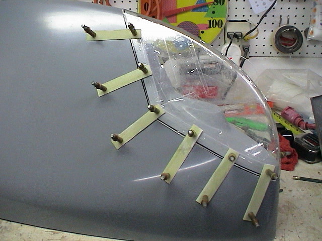
To install tip lens, place the clear lens over
the wing tip, making sure the lens follows the contour of the tip.
Mark the opening with a marking pen approximately 1/2" larger
than the lens. The size of the cut-out is not too critical.
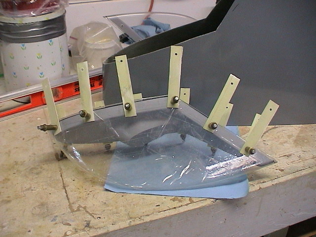
Fit the lens to the inner light moulding using six cleco's per side, these holes will be drilled out to accept MS 24694 C5 s/steel machine screws for final fit. Now take any stiff material and make 12 strips 1 1/2" x 4 (I used some strips from trimming the wings) drill one hole in each strip on one side for now to accept the cleco's and now assemble the lens and inner moulding with each of the strips protruding outward from the lens as can be seen in the picture. Now place the assembly into the cut-out in the wing tip using the fibreglass strips to hold the assembly in position once you have the lens assembly aligned, drill and cleco the opposite ends of the strips this will now hold everything in position for the next stage of assembly. Now that you have everything where you want it, take it all apart and prepare the inner surface of the wing tip around the cut-out, sand with 40 grit paper, dust off and degrease. Take your tip sens assembly and line the inside of the moulding with release tape as well as the lens to make sure it is not glassed in place permanently. This tip was designed to allow you to install a Whelen A490 A strobe power pack through the cut-out with the lens assembly removed, this prevents the need for a separate access panel. Now reassemble the lens and moulding and cover the surfaces that the fibreglass is going to come into contact with, with some release wax just to make sure everything comes apart later. Now carefull replace the lens assembly back into the wing tip cut-out making sure it is aligned. Now take a pre-wet 4 ply bid tape 3" wide and place into the rear of the lens moulding and let it overlap onto the vertical face a little for now, it will be trimmed once it is cured. Where Cleco's protrude through the flange of the tip moulding just force the bid down around the barbs, with a bit of patience you can get the glass down nice and flat around it (this is quite important as you will have to rivet K1000-08 nut plates onto this flange later, so the flatter you get it the better.). The balance of the 3" wide bid must be securely laminated into the wing tip. Once this is all cured if there is any gap between the edge of the lens and the tip cut-out just sand the edge of the gap and fill with dry micro and while still wet take a blade and cut around the edge of the lens. This gives a very nett gap around the lens. |
 |
|
 |
|
 |
|
 |
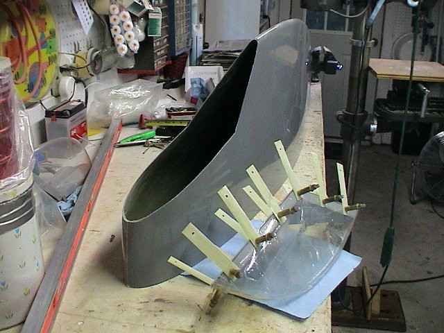
As I said, I never seem to follow directions exactly. Prior to the trial assembly I trimmed the clear plexiglass lens to just larger than the mounting. I then trimmed the wingtip opening to just larger than the assembly. After carefully positioning the lens to the opening according to instructions, I used tape to hold everything in the exaction position needed and removed all the cleco's and straps. I then reinforced the tape to make sure it was not going to come loose. |
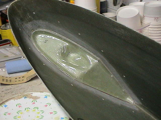 |
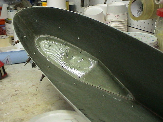
This shows the inside position of the assembly without the
cleco's just prior to the glass work. I applied the glass bids
and let it setup. The absense of the cleco's made application of
the glass much easier. After the glass cured, I drilled the holes for the screws before disassembling and removing the tape. Since the guide holes were already there, the drilling of the holes was assured to be accurate. |
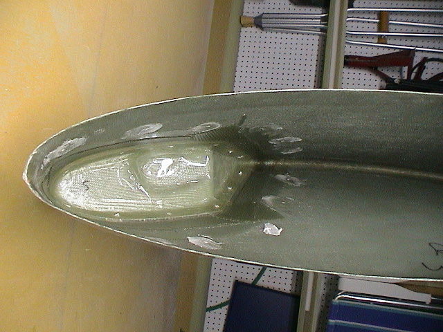 |
The glass layups have been applied and the clecoe holes have been filled. |
 |
The tape has been removed and the two parts of the wing tip have been removed. The glass needs to be trimed and cleaned up some. The holes for the screws can now be drilled and the nuts riveted on. |
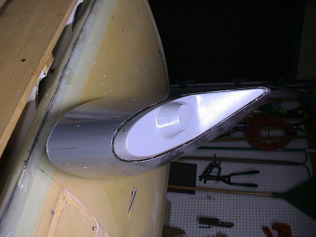 |
The inner portion of the wing tip fits neatly over the glass. Some filling will be required to finish. |
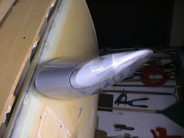 |
The fit is perfect and the completed lens cover is ready for finish. |