 Random Ideas

Random Ideas
This section will be a catch all for ideas which might be of interest to KIS builders for incorporating into their projects. These may not be of interest to everyone but could give some food for thought.
Door Handles
The door handles for the KIS as shown in the construction manual, are
not the easiest to manufacture. They also have a problem of not having
a positive spring to hold them in the open position. The following
were taken as examples of an alternative system.
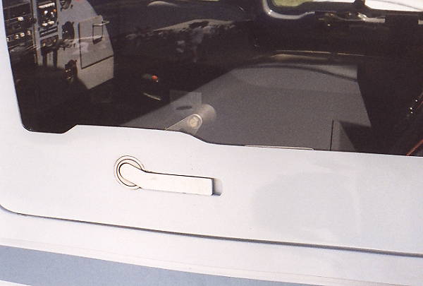 |
This is the outside view of the Lancair entry system. The inside view is below. The handle is spring loaded to hold it agains the outside of the fuselage. You catch the edge and pull outward and then rotate to open or close. |
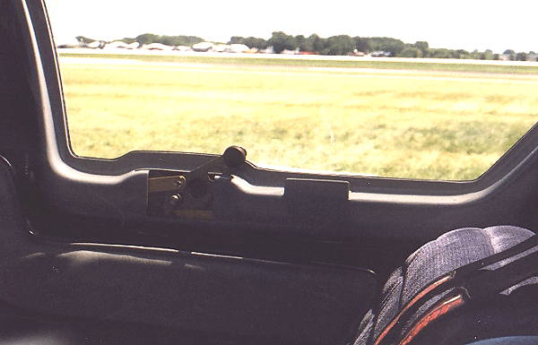 |
This is the inside view which you can see the detail of the connections to the locking bars. A lock can and often is incorporated into the handle or could be placed to catch the bar and hold it from opening. I talked to a representative at lancair who indicated they would be willing to sell the locking system but gave no indicated price. |
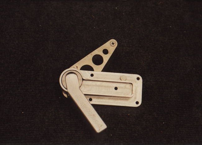 |
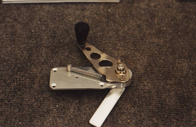
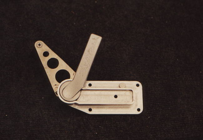
Here it is! The answer to our problem of finding a great door handle and locking mechanism. The unit shown on the left and below are in the final phases of development by Express Aircraft. I talked with them during Oshkosh 2000 and they have agreed to sell the units as soon as complete and into production. I will be in contact with Express and let everyone know when they become available and at what price. They have a very positive closure and open position which will not open or extend the closing rod when you don't want it to. |
 |
 |
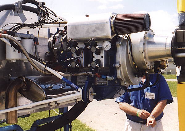
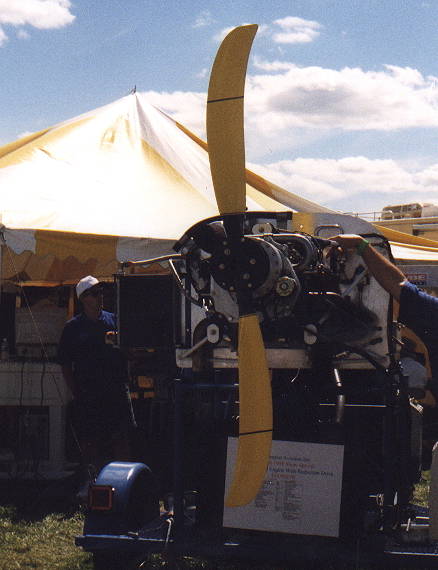
MAZDA ROTARY ENGINE & GLOBAL WARPING PROP
These photos show a Mazda Rotary Engine which is currently under development for use in aircraft operations. The engine shown develops approximately 200 Bhp and includes the ignition control system and a number of additional engine modifications to improve performance. The prop shown is the new one being designed under NASA contract and will be a quasi-constant speed prop. It is designed to have the blades warp (or twist) under load to produce a smaller angle. They then increase the angle for cruise. Good looking prop which should be available by the end of the year. Also very light and a bit expensive except when compared to a true constant speed prop.
 |
 |
 |
CONTROL SYSTEM OPTIONS
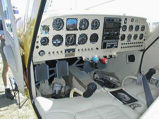
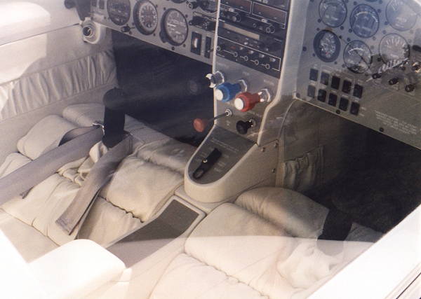
There has been a great deal of discussion regarding the control system for the KIS and especially the KIS Cruiser. Some ideas have been floated regarding the use of a center control stick instead of the dual control sticks that are standard with the project. There has also been some discussion of adjustable seats and use control sticks which would protrude thru the station 30 bulkhead and curve up to the normal position. Some examples of each of these ideas are shown in the following photos. Also shown are a couple of nice examples of the standard layout.
 |
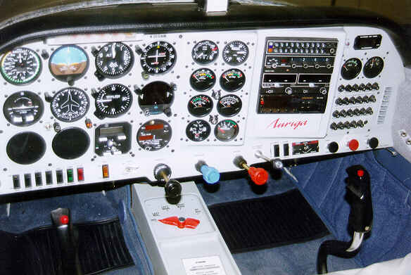
This photo and the one below show an outstanding example of the center stick combined with dual side controls for the throttle and mixture. The air vents are just above the throttle controls on the side. |
 |
The seats here may or may not be adjustable but easily could be. The controls can be reached by either pilot with equal ease. The little red knob on the throttle control is a friction adjustment. |
 |
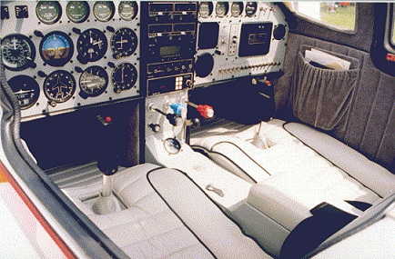
Here is another example of the center stick but as you can see has only one set of throttle and mixture controls on the pilots side. The Co-Pilot is limited to control of the entertainment system consisting of a large CD Collection. |
 |
Yet another nice example of a center stick with only pilot controls on the left side. |
 |
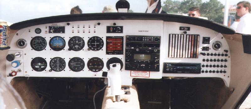
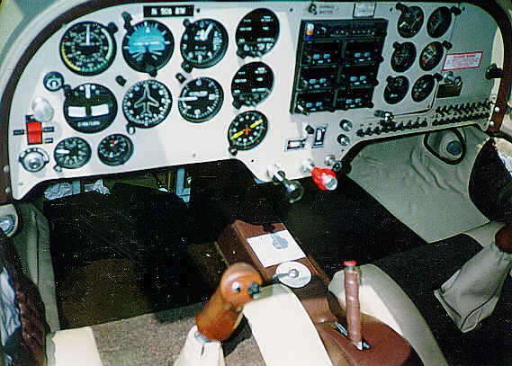
Now a great example of control sticks which curve out and up to the hand position. This would be utilized for dual sticks with the adjustable seat and the sticks going through station 30. Throttle controls in dash with fuel switch in the center console. |
 |
This is another example of the curved control stick with everything else located in the center. This example is a GlasStar but is quite similar to the KIS. |
 |
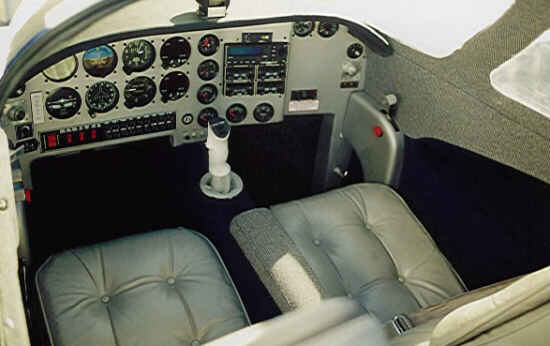
Now an example of the standard KIS styled seats and control quandrant including the center flaps control. |
 |
A very attractive example of the standard layout with nice raised center arm rest but no flap control handle. |
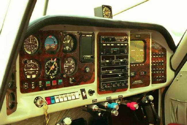 |
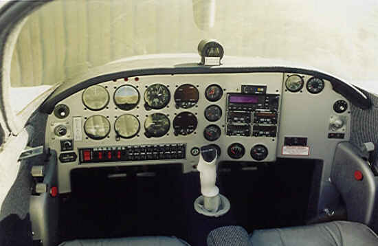
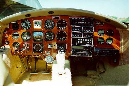
This panel shows an example of a laminated set of panels within the Instrument Panel. These panels are individually removable and are laminated wood veneer over plexiglass and a thin aluminum panel. These can be easily setup for lighting of the instruments. |
 |
Lastly, this is just such a good looking interior that I thought it worth including just for the example of how great the interior can look. |
DOOR SEAL
The door seal on both the original prototype and the one on the new demonstrator leaves a bit to be desired. I looked at a number of additional kits with an eye toward finding an alternative. The flange fot the seal is only about 1/2 inch wide (at the narrowest point) along the leading edge of the door.
 |
This photo shows the narrow flange area on the prototype door frame and the absence of any door seal. |
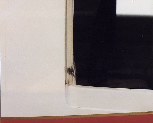 |
This shows the door seal use on Bill Grote's factory demonstrator. This is a 1/2 inch wide ribbed rubber seal which is just stuck on. You can see the damage caused by the door locking pin on the seal already. No seal is used on the bottome of the door and just relies on the overlap. |
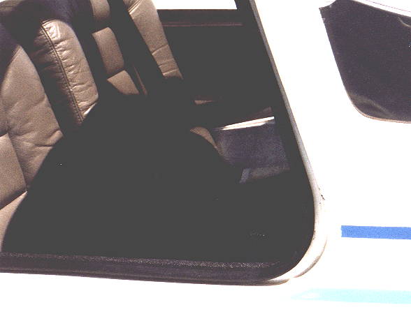 |
This example (though hard to see in this photo) uses a stiff U-channel to clamp onto the flang and includes a soft rubber channel on the outside that forms the seal against the overhead door. Other examles (now shown) use a soft rubber seal on the door instead. The door seal pressed agains the flange to form the seal. This would work on everything except the lower door flange which is shappend differently. |