 |
PAUL LAMAR - TR-4 BUILDER
Paul bought a partially completed kit and will be completing it using a Mazda Rotary Engine as the power source.
Paul also has an excellent Aviation related web site at:
http://home.earthlink.net/~rotaryeng/
Paul is also the contributing editor to the Aircraft Rotary Engine Newsletter.
(Note: The following comments were taken from e-mails provided by Paul and have been cut and pasted to fit the context of the subject as required. My thanks to Paul for some outstanding ideas and work. Bob Reed)
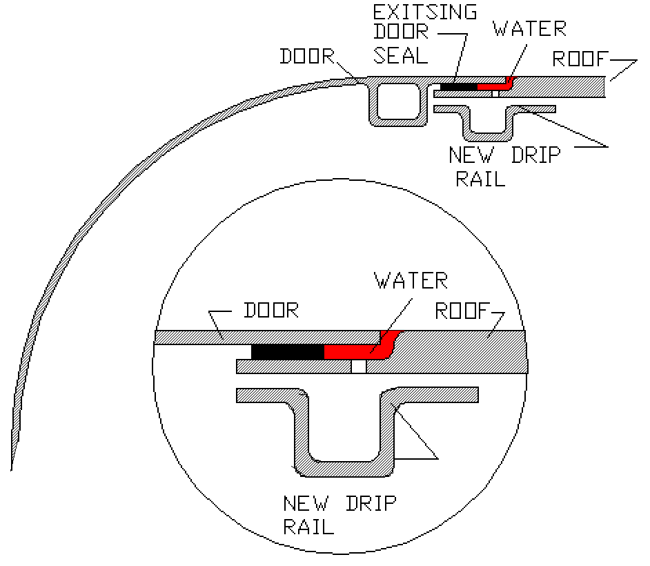
Door Drip Rail - Drawing
 |
NOSE GEAR RUBBER BUSHING
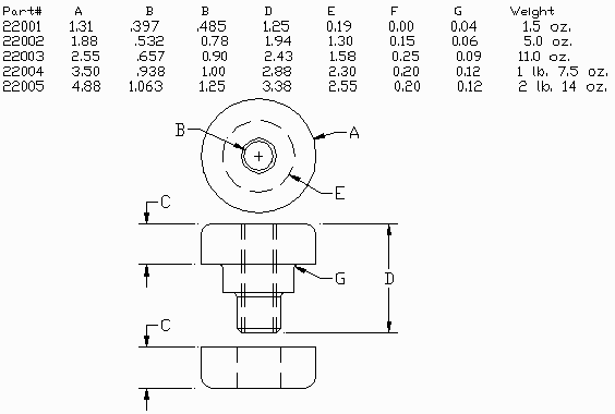
I intend replacing the nose gear shock absorber rubber bushing I got with the kit with a larger more suitible, higher rated 22001 series unit from Barry Controls. Here are the dimension and a picture. More pictures of the actual installtion shortly as I have some on order from McMaster Carr.
I don't consider the supplied shock bushing to be near the proper rating.
Paul Lamar
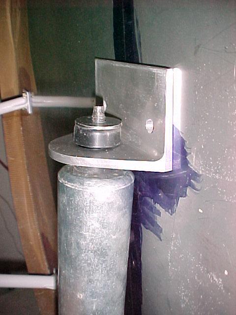 |
Here is a picture of the 22001 Barry rubber bushing installed on the
nose gear. The bracket must be drilled out with a 3/4 inch hole. I used a
hole saw.
The static load rating on this bushing is 250 pounds. Far higher than any shock absorber bushing. The next size up will give you up to 630 pounds static rating but you will have to sleeve the hole in the rubber mount steel spacer with another smaller steel spacer 1/2 inch OD with a 3/8 ID. Page 956 in the 105 Mcmaster Carr catalog. $5.50 Comes with snubbing washer. Vibration Control Mounts in the index. Paul Lamar |
| Rated Static Load Per Mount (Table) 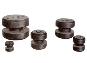 |
 |
Mazda Rotary Engine Mount
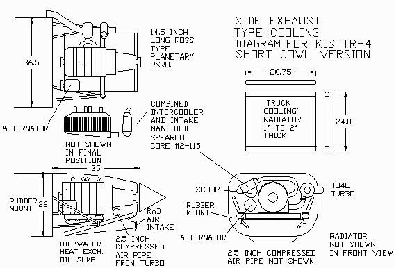
I have the drawing done for the engine so here it is. I might move the engine forward an inch or two to clear the nose gear. If that is the case I will extend the cowl behind the spinner. I choose the short cowl for CG reasons.
 |
Center Control Stick
Here is an idea for a center stick someone may be interested in. This is similar to what is found on the Pulsar and many other airplanes.
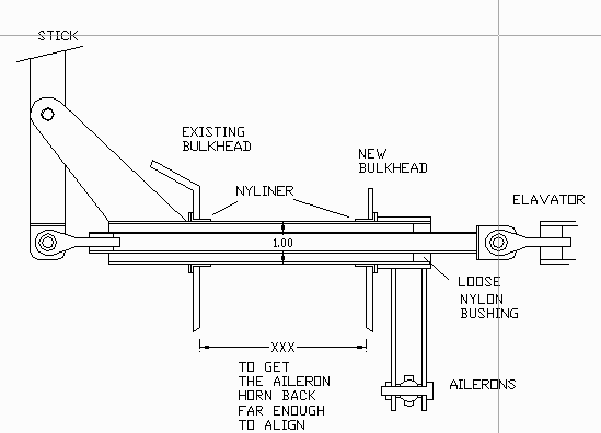 |
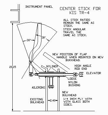
For the TR-4 and maybe the 2-plc this arrangement will result in a reverse elevator motion so a bell crank is needed behind the baggage compartment to reverse the motion of the elevator push pull rod. One of the advantages to using a reversing bell crank in the back of the airplane is most of the time the forward elevator PP tube is in tension. It takes more stick force to pull up than it does to push over. You will need some sort of support for the elevator PP tube anyway as it is too long and will buckle under compression if unsupported.
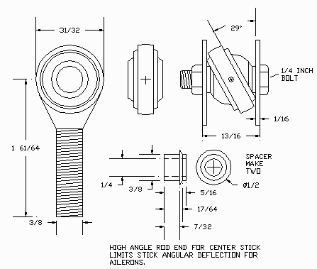
Another way of doing it is reverse the position of the horn that holds the stick so it sticks stright down if you have room. Below are additional detail drawings of the Center Stick including a High Angle Rod End which will be attached to the Elevator control rod. This is necessary to allow the full freedom of movement for ailerons control without binding or twisting the elevator control rod.
 |
 |
Vance, Rich and Mark all told me the aileron motion of the stick needs further lateral travel. By that I mean it needs a shorter lower section to apply more force to the ailerons. One could lengthen the top part of the stick but that would affect the elevator feel. I don't really know because I have not flown Bill's airplane yet. Any day now.
This whole control harmony issue is a very complicated thing. What I think is needed is an aerodynamic balance on the ailerons similar to what Cessna uses. I think just cutting off the radiused lip on the bottom of the existing aileron design would help.
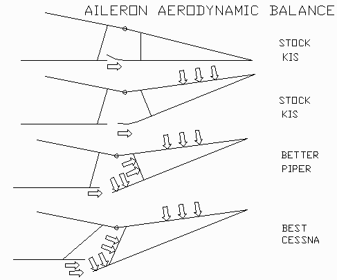 |
I will try to talk Vance, Bill and Rich into such a test.
Paul Lamar
Instrument Panel - Lighting and Mounting Setup
I am thinking of making the instrument panel of a piece of 1/4 inch plexi laminated with door skin (or wood veneer) on the front and thin aluminum on the back. That way one can use the new high brightness LED's to illuminate the instruments with sort of a fiber optic effect. The door skin will have a layer of 4 oz glass and epoxy to make it hard and water proof. The grain should still show through.
Mahagony door skin is about 1/8 inch thick plywood.Very cheap at your local lumber yard. It is also very soft wood so one layer of 4 oz glass cloth and epoxy resin will toughen it up. The instruments are mounted on the back aluminum panel. I am thinking of useing some kind of sheet metal screw through the aluminum and into the pre drilled plexi instead of instrument mounting bolts. I need to do a little testing first on this part of the design. Perhaps some threaded inserts glued into the plexi would work too. Clear Lexan might be tougher.
The lower fixed aluminum channel will hold the throttle and prop controls and probably all the circuit breaker/switches. It could be as much as three or four inches high. The upper part of the panel will hinge off this channel.
When you hinge down the panel you can also get to the back of the controls and the circuit breaker/switches.
The plumbing for the gyros's and rate of climb could be flex tubing.
I envision piano hinging it down and back 90 degrees from a fixed aluminum cross tube at the bottom. I hate working on the back of a conventional panel. Here are some drawings to illustrate.
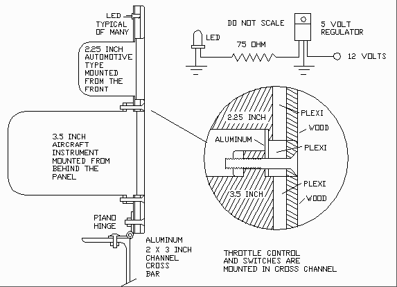
This panel uses up to a dozen highly reliable LED's. These have been known to work for years. I have a large Radio Shack LED clock that has worked non stop for twenty years.
This panel is not really fiber optic. It uses the plexi to distribute the light much as two mirrors would front to front 1/4 inch apart with three inch inst. holes in the them every here and there.
The LED's are about 5 mm in dia and you can get high brightness blue and white. Each LED consumes 120 milli watt or 0.12 watt. The current drain is 20 ma or 0.02 amp each. You can buy them at http://www.digikey.com or 1-800-344-4539.
You can connect ten or twelve in series and hook up to 12 volts or use a $2 five volt regulator from radio shack and dropping resistors on each LED. Your choice. I would go the regulator route as they are expensive for LED's at about $4 each in qty of ten. In any event don't over voltage them or they will blow.
Radio shack may have those high brightness LED's in stock these days as they are quite popular. If you use one regulator per LED you will need about a 75 ohm dropping resistor in series with the LED.
I have not experimented but I suspect that shiny al-clad aluminum for the back and the front might enhance the face to face mirror effect. You can still glue on the veneer or plywood.
Paul