 |
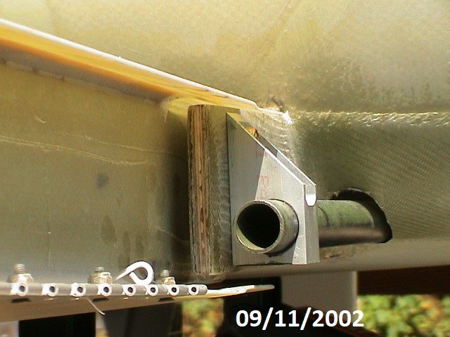
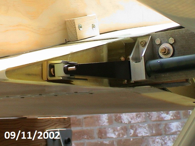
The builders manual talks about the space between the rear
spar and the wing rear spar. You can see the space clearly in
this photo and the relation to the flap control rod hangar. I was
very concerned about this due to a mistake I made in installation of
the rear spar. I installed it perfectly vertical instead of the
directed 3 degree angle. It proved to be a non issue since the
gap is more than large enough to allow for compensation. |
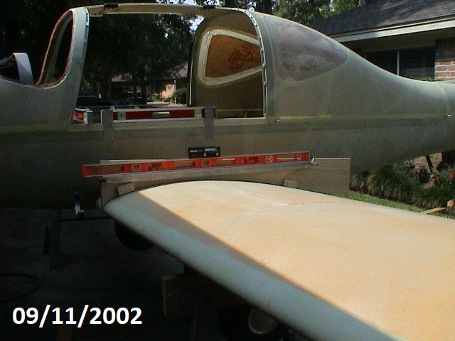 |
The wing alignment jig is placed on the wing and the
positions marked at the same point on both wings. If the jig is
made according to the template and adjusted to fit the position the
same on both wings the top edge of the jig will be at 3 degrees when
the level line is level. By dang, it worked!
I used a 2x2 aluminum angle clamped on the level line and
then placed a level on that. I set the smart level on top and
used the tone generator to let me know when it was level.
|
 |
First, I created spacer blocks from 1/4 " Phenolic sheet
and placed them between the rear spars. I positioned the left
wing first and adjusted the rear spar up or down until it was
positioned correctly. It was clamped into place and I moved to
the right wing. I repeated the process to ensure that I could get
the correct setting on both wings. Once sure of the settings, I
drilled pilot holes and installed guide bolts and rechecked everything
again. I proceeded then to enlarge the spar bolt hole until it
was ready for the bolt and guides. |
 |
Once the spar bolt holes were set and checked, the spacers
and bolt guides were all bonded into place, the rear spar bolt
installed and tightened while the adhesive set.
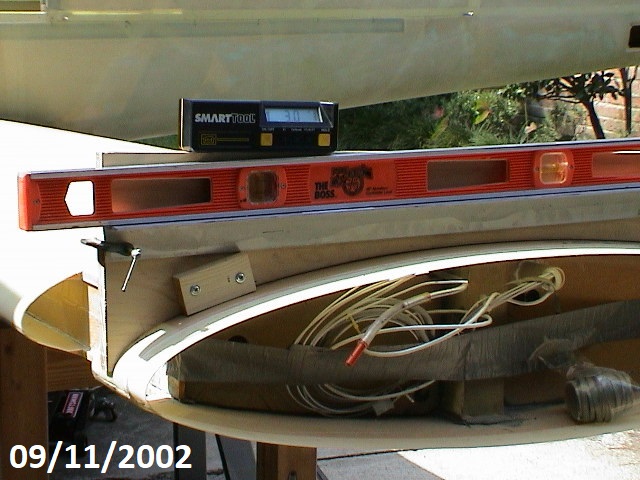
I checked the angle of incidence at both the wing root
and wing tip. The SmartLevel is shown setting on the jig and I
think you can see the angle shown is exactly 3.0 degrees. I was
lucky enough to see the exact same readings on both wings.
It's great to be lucky!
|
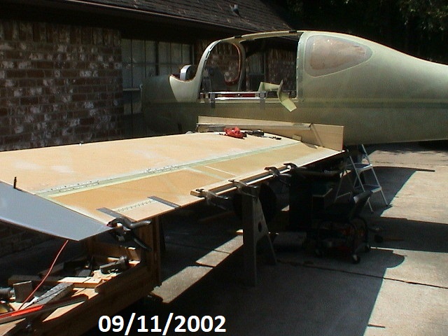 |
Once the angle of incidence is set it's time to install
the wingtip, ailerons, and flaps. I used clamps to hold the
aileron and flap into proper position for alignment and checking the
tip alignment. |
 |
I had already installed the inside flap control arm but
waited to install the forks on the end of the flap control. This
allowed me to position the flaps, align the control fork and then mark
and drill the bolt holes for the control arm. I believe this
better compensates for any misalignment in the flap guides. Also
note a 1/4 " phenolic spacer behind the guide. I don't know if I
made a mistake or what but the nylon guide just wasn't making enough
contact for my part. |
 |
Once the Flap positions are set, the fairings can be fit.
Allow plenty of time for this process. It is totally a
trial and error process to get the right fit. I placed 3 layers
of duct tape over the recessed flange on the wing before starting.
I wanted to make sure there was some clearance for sliding the
wing on and off. |
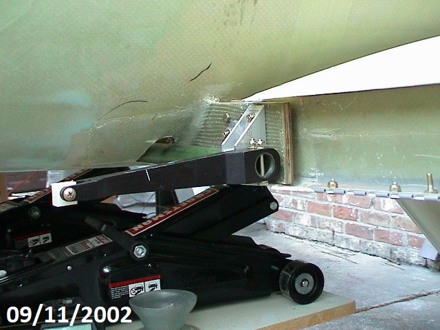 |
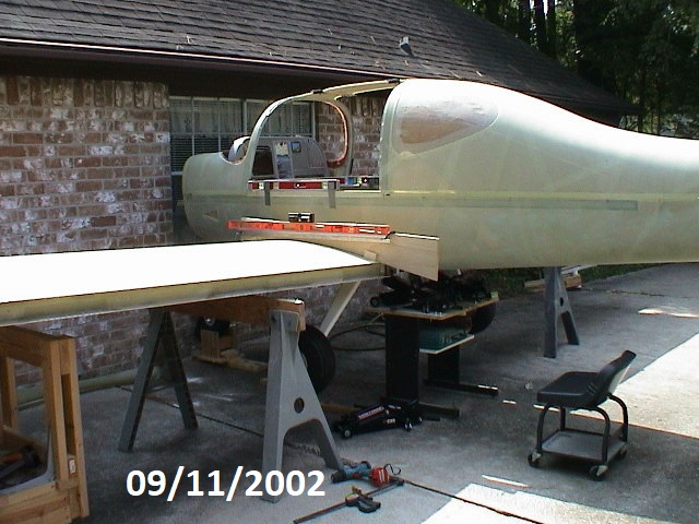
The right side spar control arm is shown in the full up
position. You can see the jacks used for adjusting and holding
the fuselage level. |
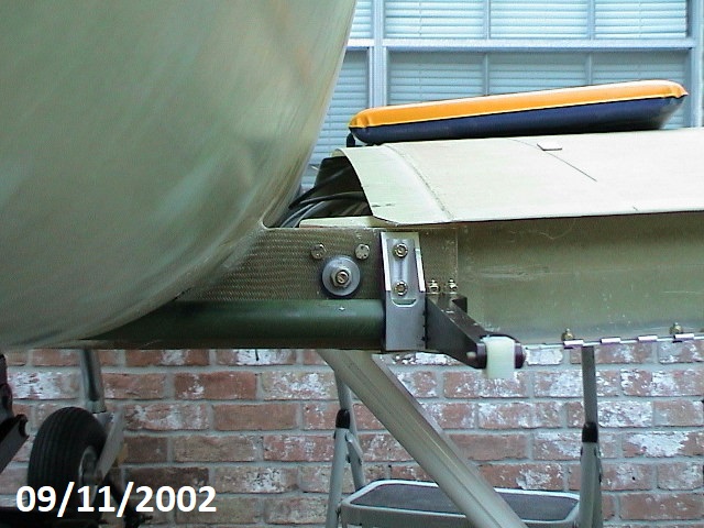 |
This shows the bolts for holding the rear spar to the rear
wing spar. The two bolts at the top are just guide bolts but I
will leave them in. They are not necessary but made it easier to
hold the spar in position while drilling out the main spar bolt holes. |