Tri-R Technologies TR-4
BUILDER'S MANUAL
This Builder's Manual is NOT the official manual as published by TRI-R Technologies.
PUSH PULL TUBES
ASSEMBLY
Quick Links to Aileron Assembly Sub-Sections:
AILERON
PUSH TUBE ASSEMBLIES
FLAP ACTUATION
ROD ASSEMBLY
ELEVATOR PUSH TUBES
RUDDER ACTUATION
TUBE
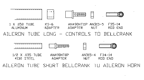
There are two actuation rod assemblies in each wing half. The long actuation rods transfer motion from the idler crank driven by the stick control system to the bellcranks mounted in the leading edge compartment in the outboard section of each wing. The shorter rods transfer motion from the bell cranks to the aileron control "horn".
The long aileron rods are assembled using 1 inch diameter aluminum tube and components shown in the top sketch. the rod ends for these "push rods" have a 5/16 female thread and end bore for a #10 (.190in) bolt. The AN adapter requires a ks -6 sleeve to fit the supplied tube size.
Set tube length by making a trial assembly of the components. Screw the rod end to the bottom of the threads and back off roughly 5/16th inch and set tube length for rod end center to center distance required . The assembly should be secured with two 1/8 inch diameter aluminum rivets located 90 degrees apart. Some adapters have a hollow section where it is inserted into the tube. If this is the case fill this hollow with a flox micro mix to keep the rivets from buckling when the end is "set"
The short tube as shown in the lower section of the sketch is made up using a 1/2 diameter steel tube, and the components show in the sketch. The rod ends for this assembly have a 1/4 inch female thread with end bore for a #10 (.190 in) bolt. Assemble as before with four aluminum rivets in a crossed pattern.
The aileron system also has a pair of short actuation rods between the stick assembly and the aileron idler in side the fuselage. These rods are made up using ¼ inch threaded rod and twoF34-14 rod ends and check nuts

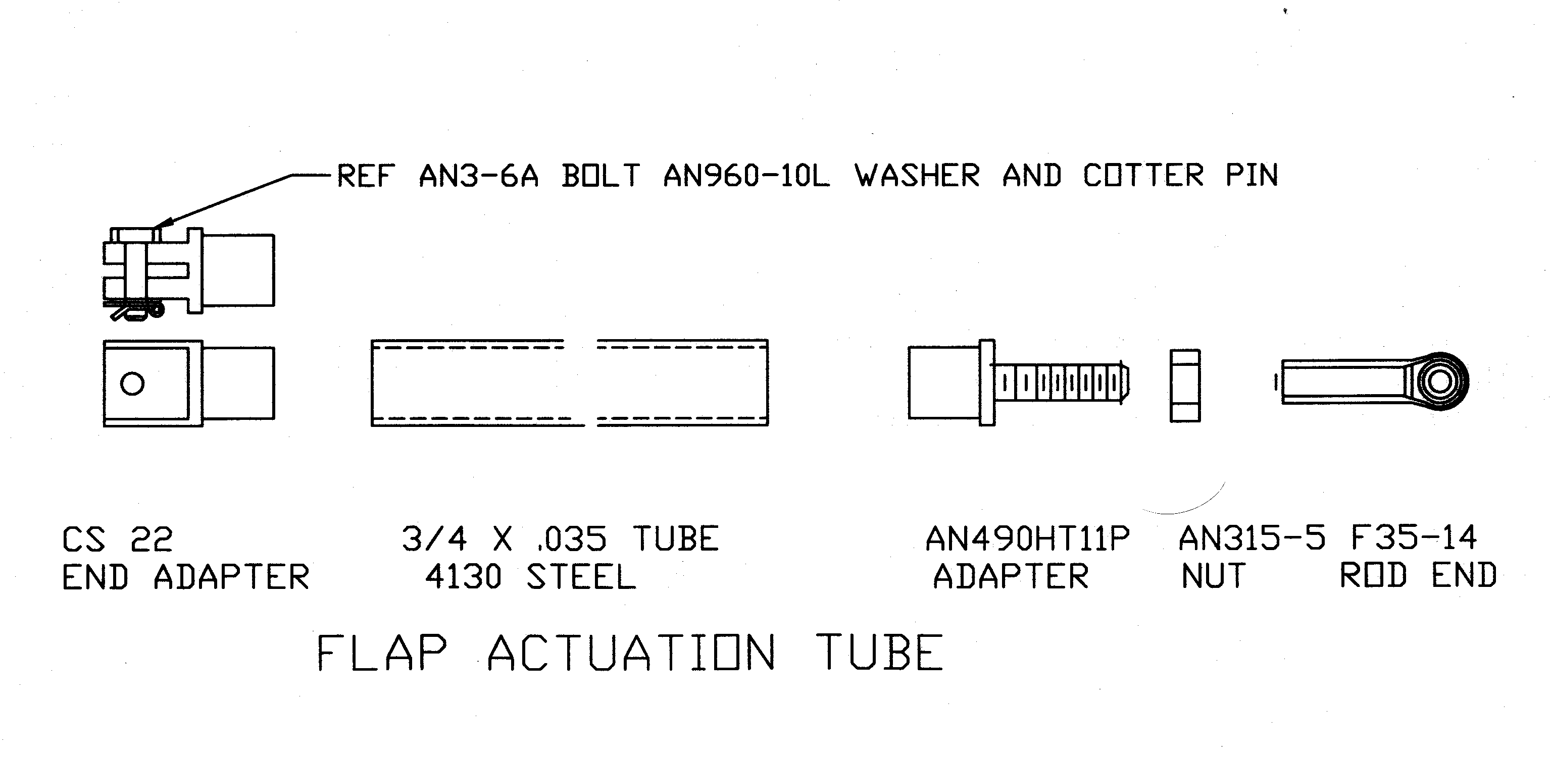
The flap actuation rod (connecting the flap actuation handle and the actuation arm on the flap torque tube) is assembled utilizing a section of ¾ inch diameter steel tube. The space between the flap actuator handle sectors is quite restrictive, so a short bolt is used as a pin using only a washer and a cotter pin.

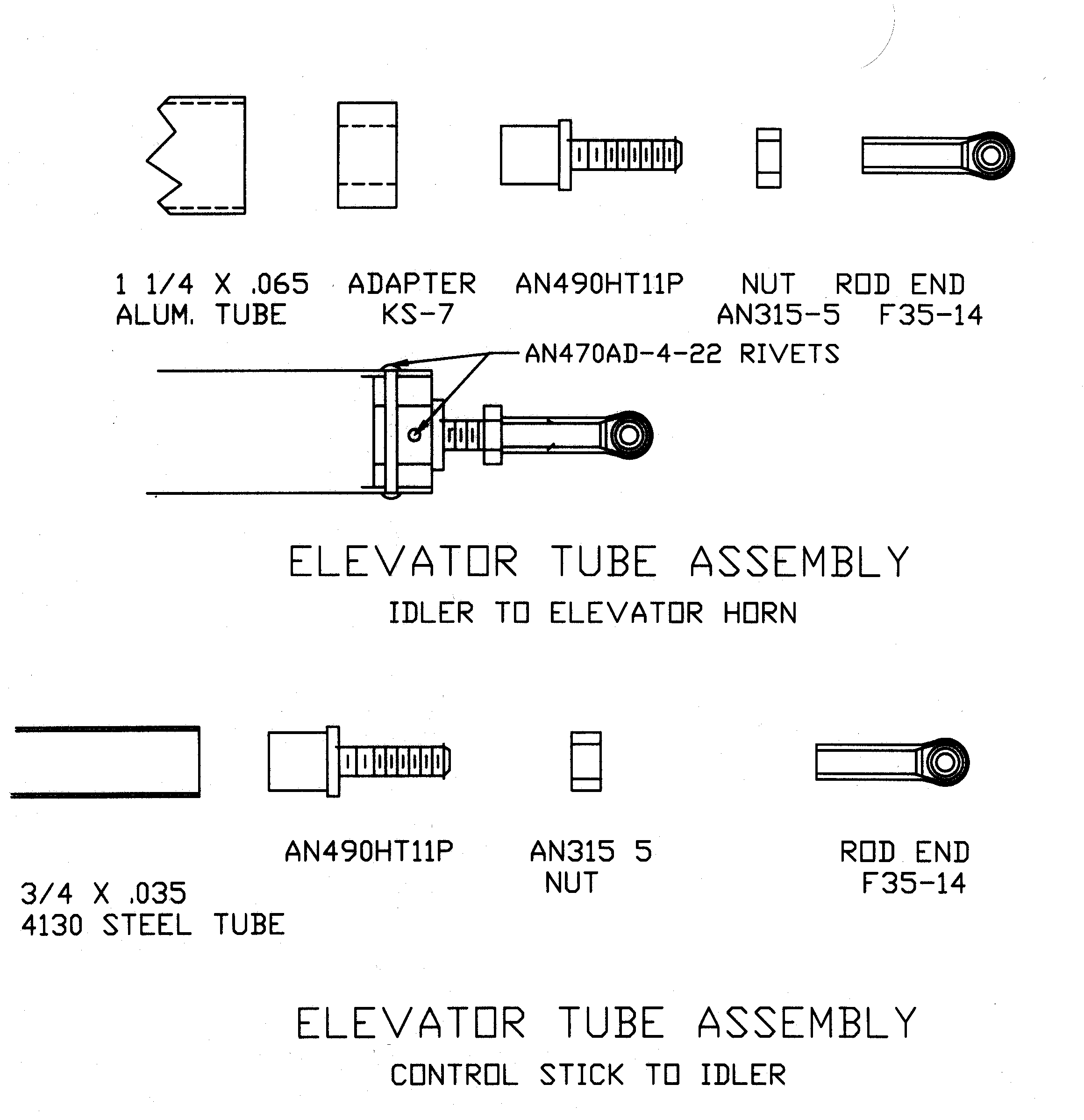
The elevator actuation system consists of two tube sections. The first connects the stick to the mid fuselage idler crank, and the second section runs from the idler to the elevator "horn". The materials and components are shown in the drawing below.

The rudder system utilizes a push tube from the cable operated bell crank idler and the rudder "horn". This tube is assembled just like the shorter aileron push tube except ½ inch diameter aluminum tubing is used because of the short run.