 |
Construction of front & rear seats
William Schertz, Sept, 2000
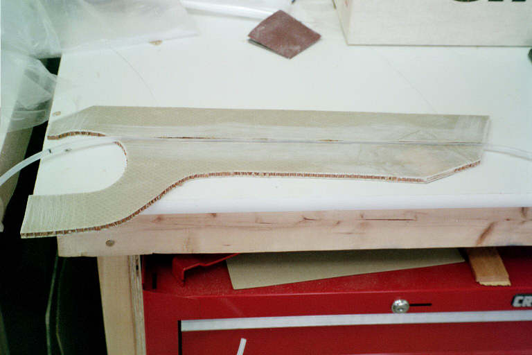
Figure 1 shows the poly tube being bonded into the inside of the front console side so that it will be out of the way. The manual just says to bond them to the sides, but between the front seats, I actually buried them into the ¼" wall structure by cutting away the skin and removing the honeycomb. This makes a neater installation. Note: 2-ply bid not in place yet, the tube is just positioned prior to bonding in place.
|
Figure 1
The console extends back through the rear seat compartment also. This next photo shows the sides being bonded in, and the structure for reinforcing the front seat. Peel ply still in place. Note that the tubing for the rudder controls is not buried in the wall back here. No flap handle to foul the lines, etc. You can also see the fact that I built up the front edge for the rear seat, having seen Bob Reed’s example on the Web. Also note that the sides of the console beside the rear seat locations are removable to allow access to the flap torque tube and lever arm, in discussion with a fellow builder, he suggested making one of the sides bonded in place, to increase the rigidity of the structure (because of landing gear tunnel). I may do this before I am done, but not yet.
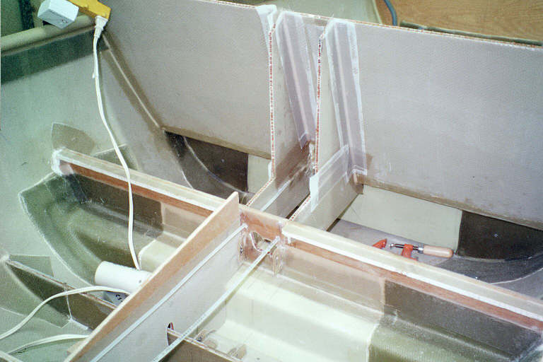 |
Figure 2
After installing the consoles, I then worked on the seats, fabricating the seat bottoms and making the seat backs fold. Figure 3 shows the lay-ups going from the center (foldable) section of the front seats overlapping the stationary parts. Appropriate use of the release tape allows this to cure in place, and it fits very well. The seat back flange is actually on both the front and back of the structure to make a sandwich that avoids "peel problems".
You can also see the plywood templates that I made to test the size for the seat bottoms.
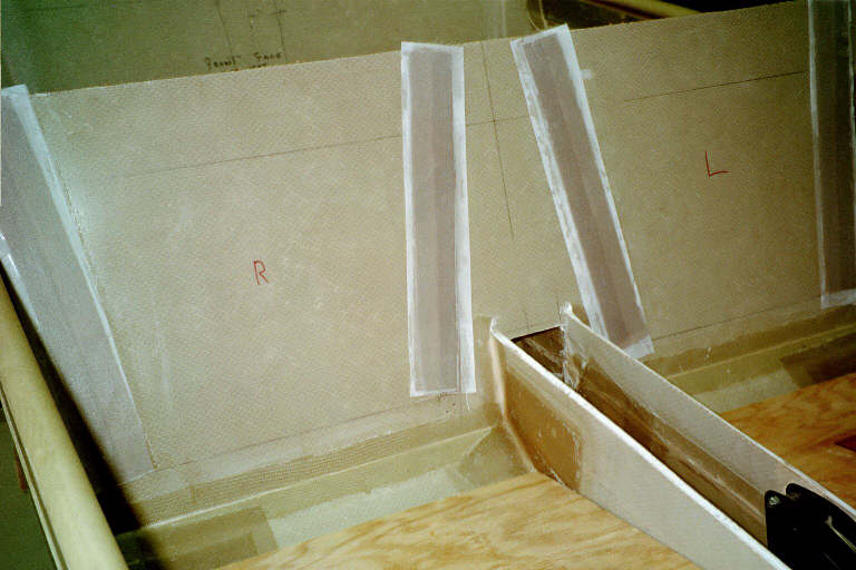 |
Figure 3
| Close-up of stationary part of flange to support seat back, The fiberglass flange overlaps the back of the stationary part of the seat, and sticks out to catch the movable part. A layer of 2-ply bid then overlaps from the front side to relieve the joint of "peel forces". | 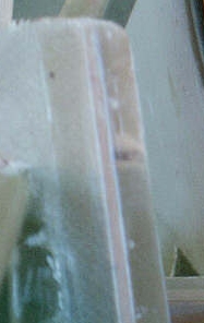 |
The front and back seat bottoms were constructed using the ¼" white foam supplied with the kit, with a 2ply bid over the top and bottom. In addition, supporting ribs were bonded to the bottoms of the seats. For the front seats, two blue foam (polystyrene) ribs were sanded to shape and covered with 2-ply bid on the bottom, then before the top bid was cured, I covered it with plastic and weighted it down with sandbags to make it conform to the shape of the front.
 |
Figure 4
Here are the rear seats being fabricated, and you can see the flat top surface, and the reinforced egg-crate of balsa wood on the bottom surface. Each seat, with fiberglass, foam, and reinforcement weighed ~2#.
 |
Figure 5
In Figure 6 below, you can see the reinforcement and the way in which the rear seat bottom folds up for access to a concealed storage area. You can also see the "T" nuts that I used to attach the seat bottoms and backs to the hinges. Works well for a non-structural part of the plane, however, don’t use on parts that carry important loads. (Even if those fasteners failed, the seat can’t go anyplace)
 |
Figure 6
The rear seat also folds across the entire back, and if I am careful with thickness of cushions, it will fold flat, allowing easy access to the luggage area, as well as allowing unwieldy sized objects to be carried (within weight and balance of course). Again the "T" nuts have been used for the hinges, don’t stick out and snag things, and not in a structural area.
 |
Figure 7